Electrical/Garage Shift Procedure
ELECTRICAL/GARAGE SHIFT PROCEDUREPerform a preliminary test before a road test in order to make sure the electronic control inputs are connected and operating. If you do not check the inputs before operating the transaxle, you could misdiagnose a simple electrical condition as a major transaxle condition.
A Scan tool provides valuable information and must be used on the VT25-E transaxle for accurate diagnosis.
1. Make sure the gear selector is in Park (P) and set the parking brake.
2. Install Scan tool.
3. Start the engine.
4. Verify the following signals are present:
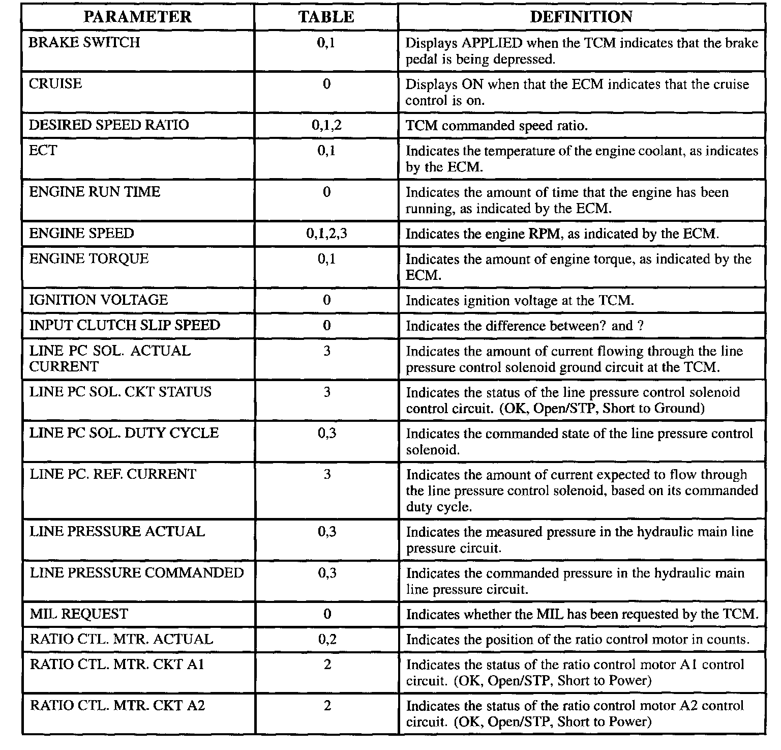
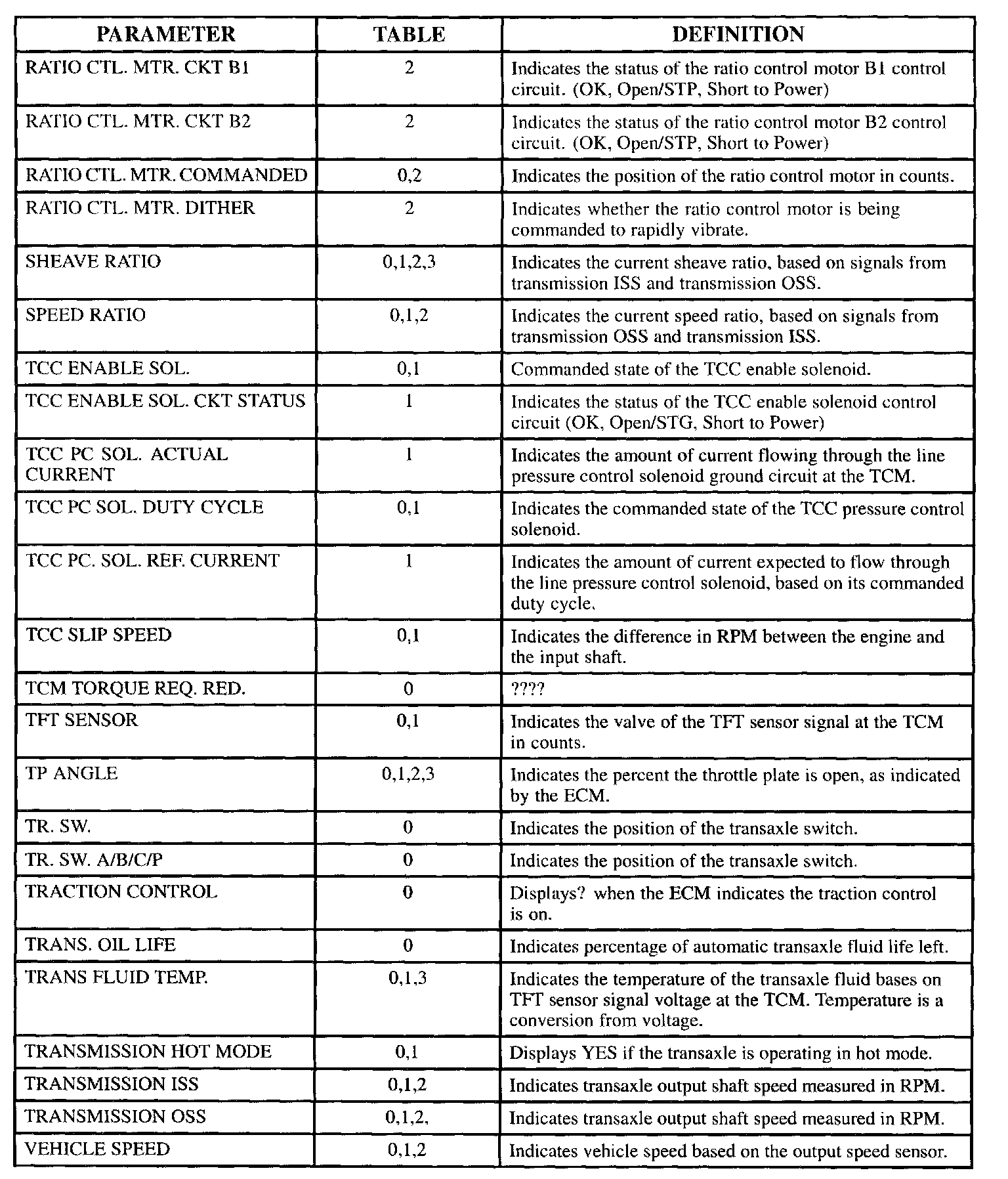
The transaxle data definitions are intended to assist in understanding the data displayed by a Scan tool when it is communicating with the TCM. A thorough understanding of this data will not only aid in diagnosing transaxle related problems, but will also help eliminate unnecessary repairs.
Parameters are in alphabetical order.
Table #0: Transaxle Data List
Table #1: TCC Data List
Table #2: Ratio Control Motor Data List
Table #3: PC Solenoid Data List
5. Monitor the brake switch while tapping the brake pedal with your foot. The brake switch should be on when the pedal is depressed. The brake switch should come Off when it is released.
6. Monitor the transaxle range switch (TR SW) signal and move the gear selector through the ranges. Verify that the transaxle range switch value on the Scan tool matches the gear range selected. Gear selection should be immediate and not harsh.
7. Move gear selector to neutral and monitor the throttle angle (TP ANGLE) signal while increasing and decreasing engine rpm with accelerator pedal. The throttle angle should increase with engine rpm.