Brake Shoe: Service and Repair
Brake Shoe Replacement
Disassembly Procedure
Caution: Avoid taking the following actions when you service wheel brake parts:
- Do not grind brake linings.
- Do not sand brake linings.
- Do not clean wheel brake parts with a dry brush or with compressed air.
Some models or aftermarket brake parts may contain asbestos fibers which can become airborne in dust. Breathing dust with asbestos fibers may cause serious bodily harm. Use a water-dampened cloth in order to remove any dust on brake parts. Equipment is available commercially in order to perform this washing function. These wet methods prevent fibers from becoming airborne.
1. Remove the tension from the park brake system.
Caution: Ensure that the vehicle is properly supported and squarely positioned. To help avoid personal injury when a vehicle is on a hoist, provide additional support for the vehicle on the opposite end from which the components are being removed.
2. Raise the vehicle on a hoist.
3. Remove the rear wheel and the tire assembly.
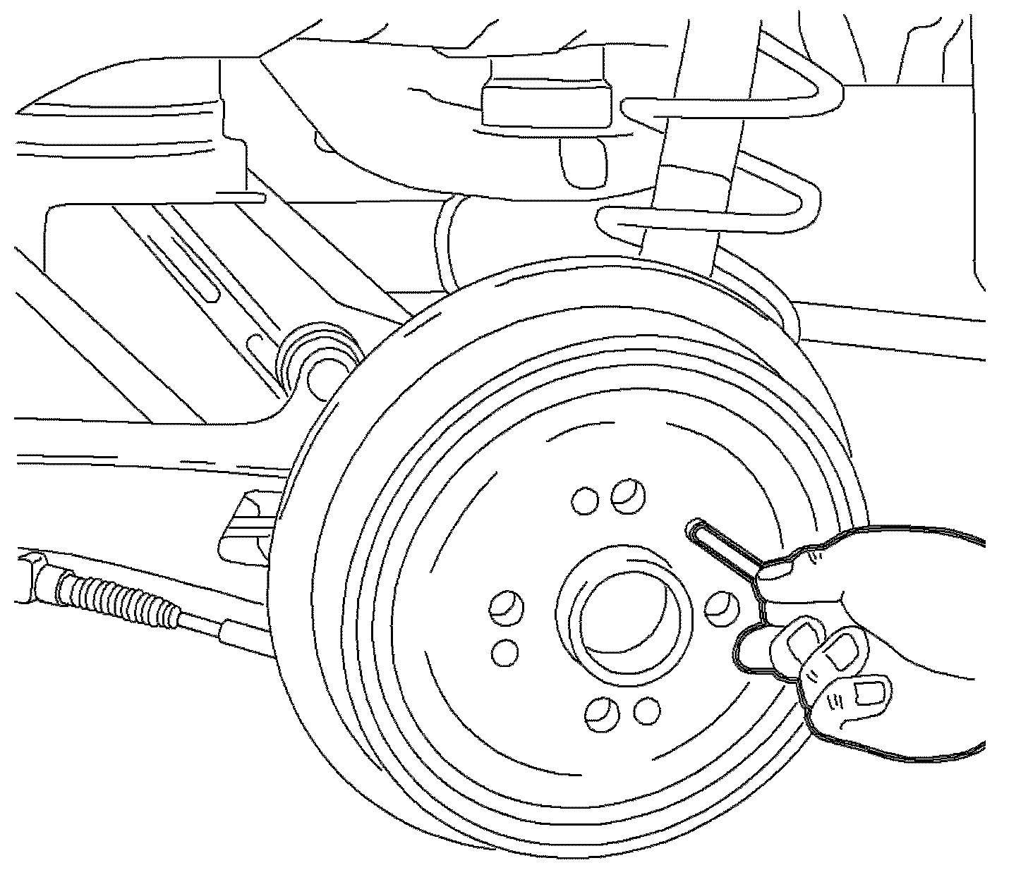
4. Remove the brake drum retaining screw.
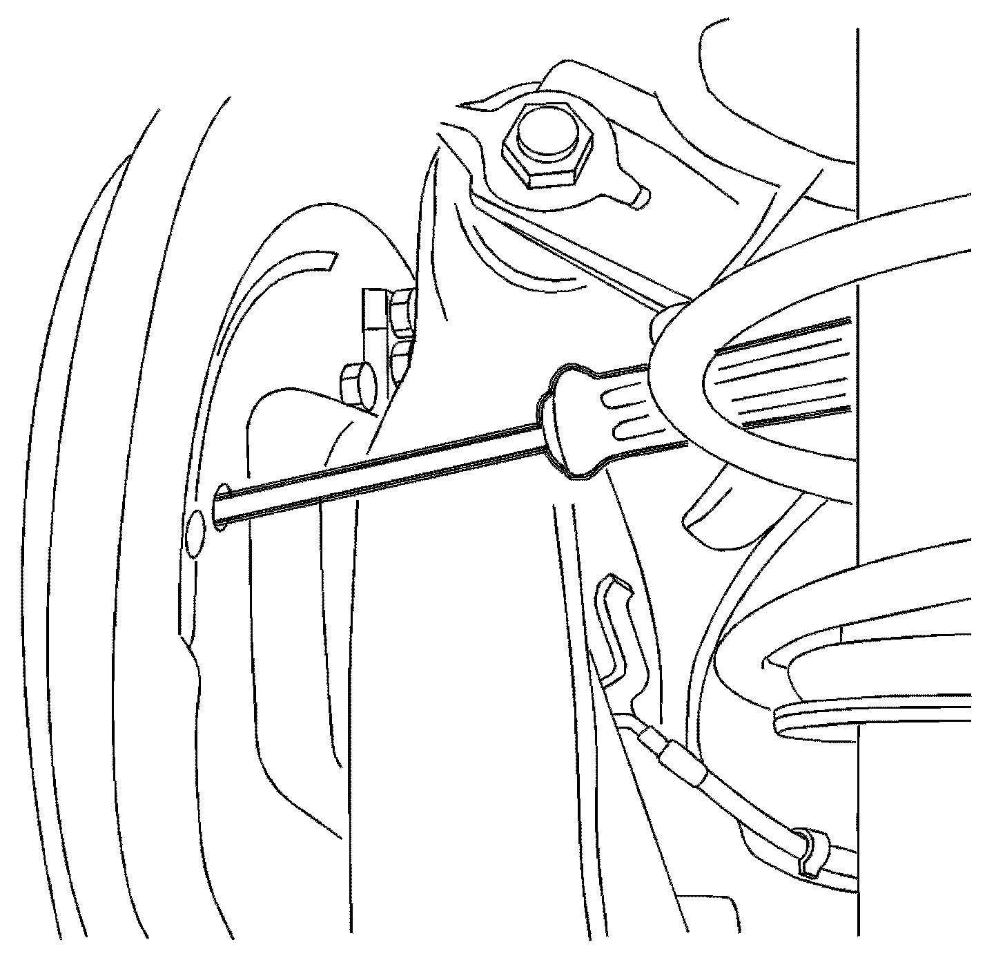
Notice: Do not pry against brake backing plate. This will bend plate.
5. Remove the rear drum.
Important: If difficulty is encountered removing the drum, the following steps apply.
5.1. Insert a screwdriver in the access hole and push the park brake lever toward the outside of the drum to release the shoes from the adjuster.
5.2. Remove the brake drum.
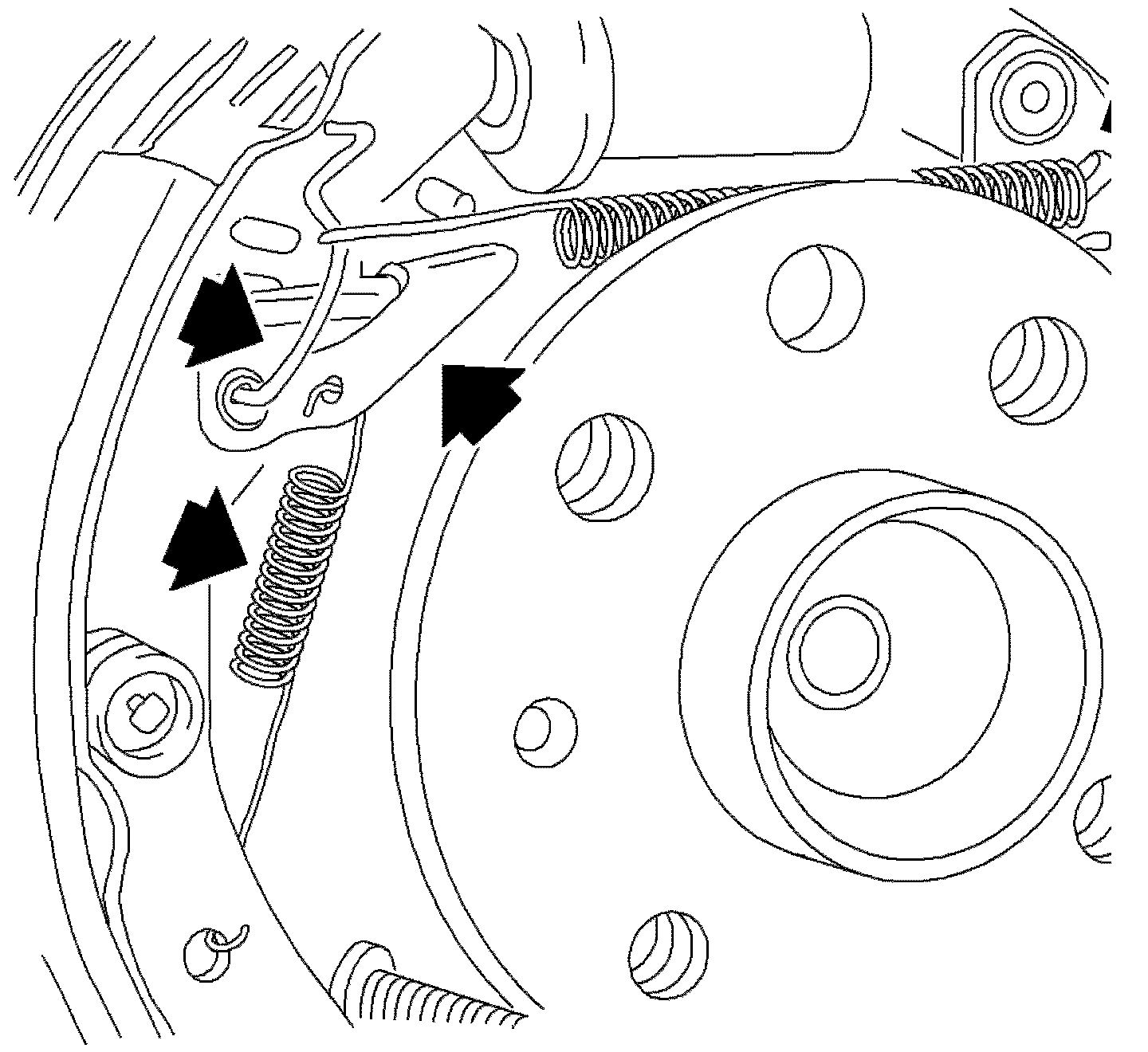
Notice: Do not over extend the springs. Over extending will weaken the springs.
6. Remove the upper return spring.
7. Remove the upper return spring retaining bracket.
8. Detach the adjuster lever and the spring.
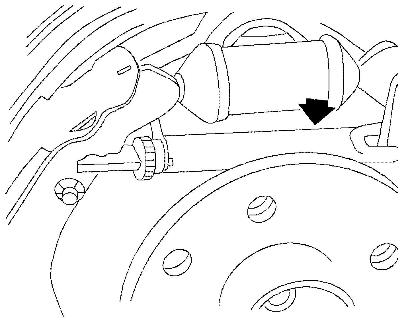
9. Pull the brake shoes apart slightly and remove the adjuster unit.
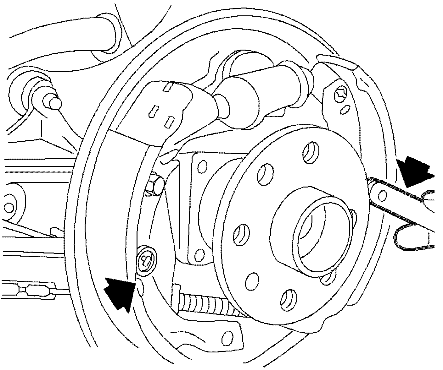
10. Remove the brake shoe hold down springs and the pins.
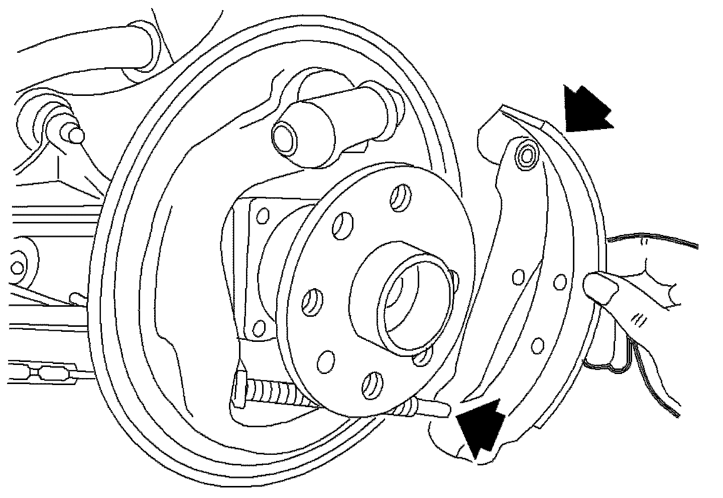
11. Remove the leading (front) brake shoe and the trailing (rear) brake shoe from the park brake cable.
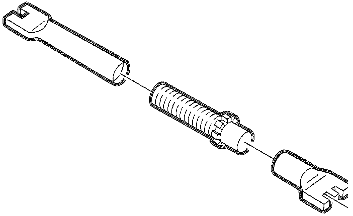
12. Disassemble the brake adjuster components: the adjusting socket, the screw, the clip, and the nut.
13. Clean the adjusting socket, the screw, and the nut in clean denatured alcohol.
14. Inspect the adjuster assembly, making sure that the adjuster screw threads smoothly into the adjusting nut, over the full threaded length.
Notice: If wheel cylinder is found to be damaged, replace it. Do not attempt to repair wheel cylinder.
15. Inspect the wheel cylinder for leakage, cuts or damaged boots. Also, make sure that the wheel cylinder is not seized.
Assembly Procedure
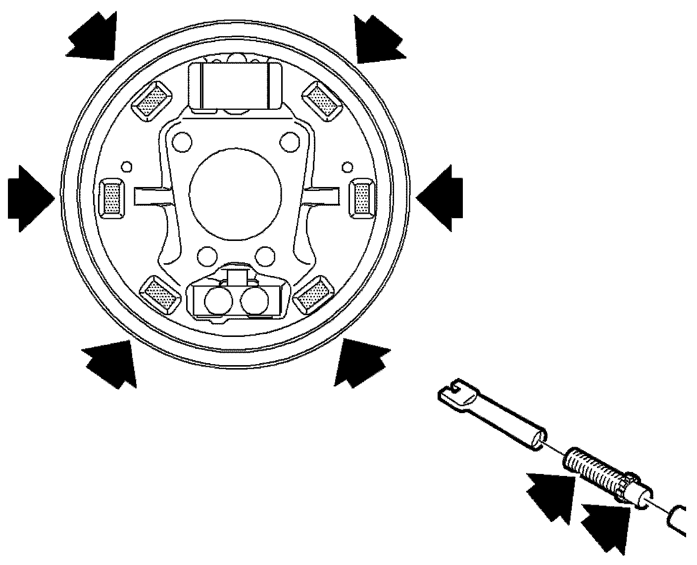
Important: When replacing the rear brake shoes, inspect the backing plate for excessive wear at the 6 raised shoe contact pads. Excessive wear at the raised shoe contact pads, such as notches or deep grooves, could impede shoe travel.
Important: Never replace the brake pads on one side of the axle only. The left and right side brake pads must be replaced only as axle sets.
1. Lubricate the following components:
- The adjuster lever surfaces that rub on the brake shoe web.
- The backing plate at the 6 raised shoe contact pads.
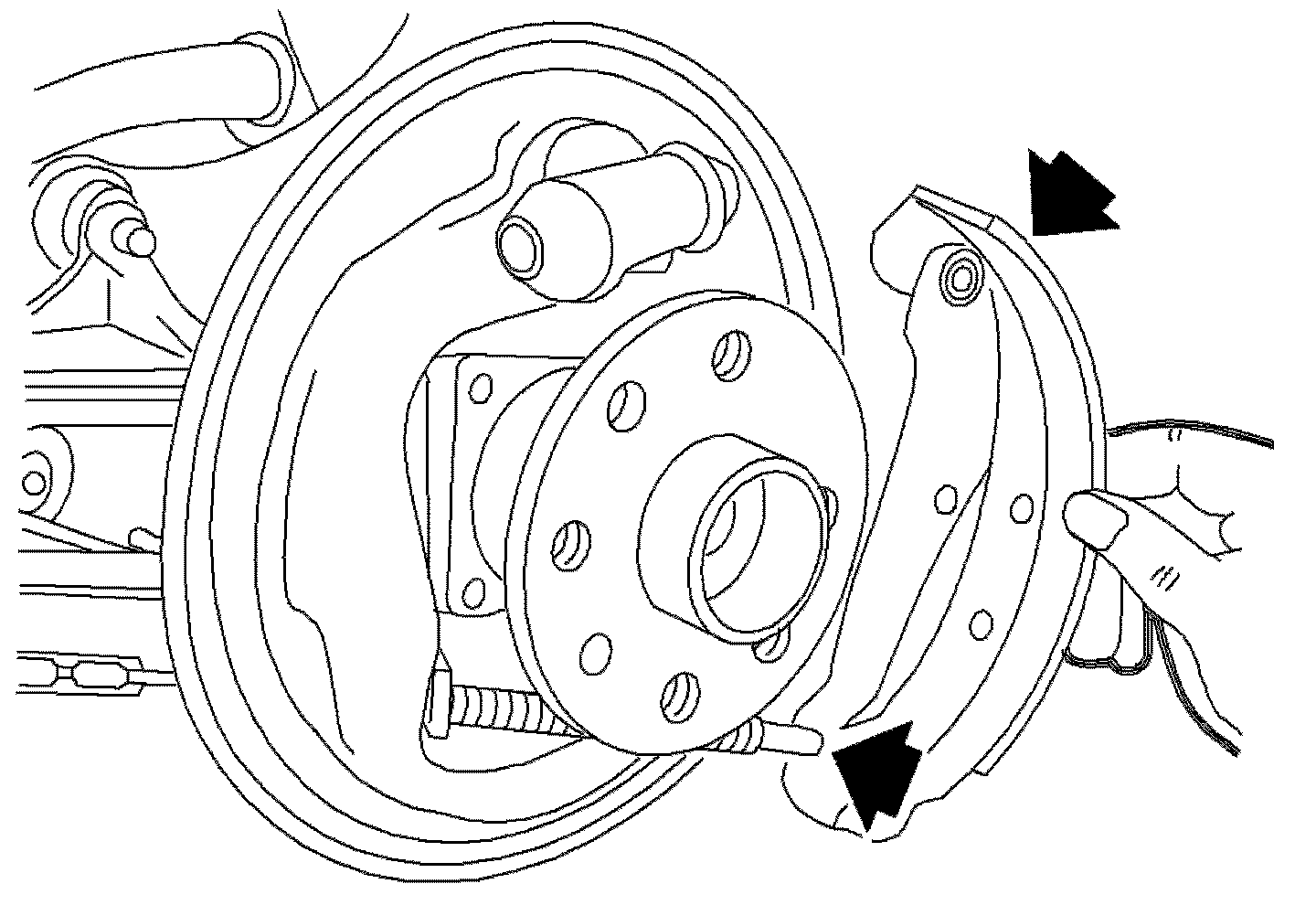
2. Install the park brake cable to the park brake lever of the trailing (rear) brake shoe.
3. Install the trailing (rear) brake shoe to the backing plate using the hold down pin and the retaining spring.
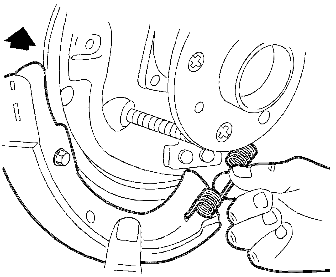
4. Attach the lower retaining spring and install the leading (front) brake shoe, the hold down pin, and the retaining spring.
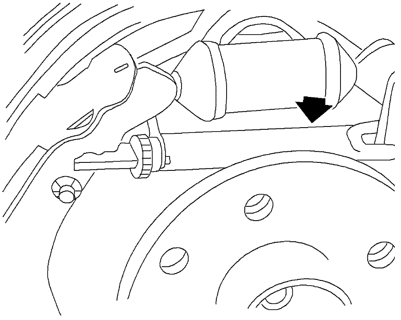
5. Slightly pull apart the brake shoes and install the adjuster unit.

6. Install the adjuster lever with the spring.
Important: Check that the brake shoe is correctly engaged in the wheel cylinder at the top and the anchor at the bottom.
Important: Check that the adjuster notches properly engage in the brake shoe notches.
7. Install the retaining bracket and install the upper return spring.
8. Adjust the drum brake shoes. Refer to: Drum Brake Adjustment
Notice: Use the correct fastener in the correct location. Replacement fasteners must be the correct part number for that application. Fasteners requiring replacement or fasteners requiring the use of thread locking compound or sealant are identified in the service procedure. Do not use paints, lubricants, or corrosion inhibitors on fasteners or fastener joint surfaces unless specified. These coatings affect fastener torque and joint clamping force and may damage the fastener. Use the correct tightening sequence and specifications when installing fasteners in order to avoid damage to parts and systems.
9. Install the brake drum and the retaining screw.
Tighten
Tighten the brake drum retaining fastener to 4 Nm (35 lb in).
Notice: Before installing wheels, remove rust or corrosion from wheel mounting surfaces and brake rotors/drums. Failure to do so can cause wheel nuts to loosen in service.
10. Install the wheel and tire assembly. Refer to Tire and Wheel Removal and Installation in Tires and Wheels.
11. Lower the vehicle from the hoist.
Caution: Prior to operating vehicle, depress brake a few times. If this operation is not carried out, brakes will not operate during initial brake applications and may cause an accident resulting in personal injuries.
12. Apply and release the brake pedal 20 times to allow the adjuster to position the brake shoes.
13. Adjust the park brake cable. Refer to: Adjustments