Road Test Procedure
ROAD TEST PROCEDUREThe TCM calculates the speed ratio based primarily on two inputs: APP angle and transaxle output speed. When the TCM says an increase in the speed ratio should occur, an electrical signal goes to the ratio control motor which in turn moves the ratio control valve. The lever on the variable ratio control valve pulls the valve into a position which allows Line I fluid to enter the primary feed circuit. The primary feed fluid is routed to the apply piston cavities and the fluid
pressure moves the piston side of the pulley towards the stationary half of the pulley. The drive belt reacts to the drive pulley position change by rising between the two sides of the pulley. Ratio changes begin as soon as the drive belt moves higher between the pulley halves.
^ Perform the road test using the Scan tool.
^ Perform this test when traffic and road conditions permit. Observe all safety regulations.
1. Install Scan tool
2. Start engine
3. Depress brake pedal. Move gear selector as follows:
3.1. Park to Reverse
3.2. Reverse to Neutral
3.3. Neutral to Drive
The gear selection should be immediate and not harsh.
4. Set up Scan tool to monitor the APP Angle and Transmission OSS and Speed Ratio.
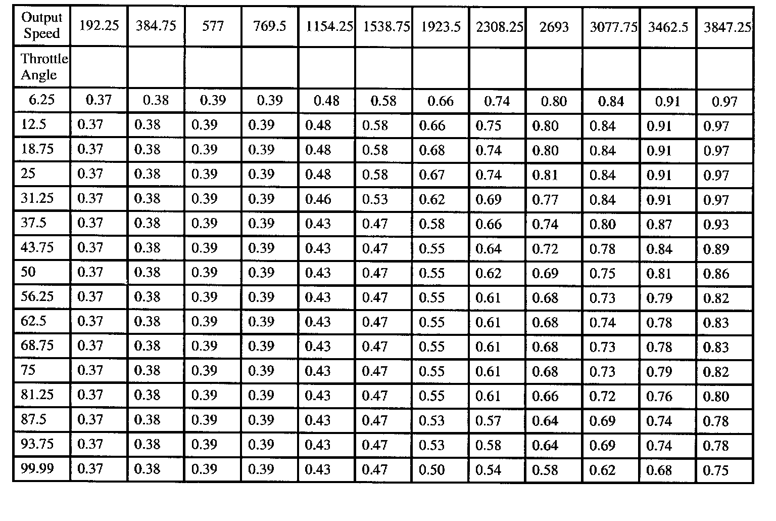
RATIO CHART FROM STOP
5. With the gear selection in Drive (D), accelerate to a chosen throttle angle and hold throttle steady. Compare output speed and speed ratio to a chosen throttle angle on the Ratio Chart From Stop.
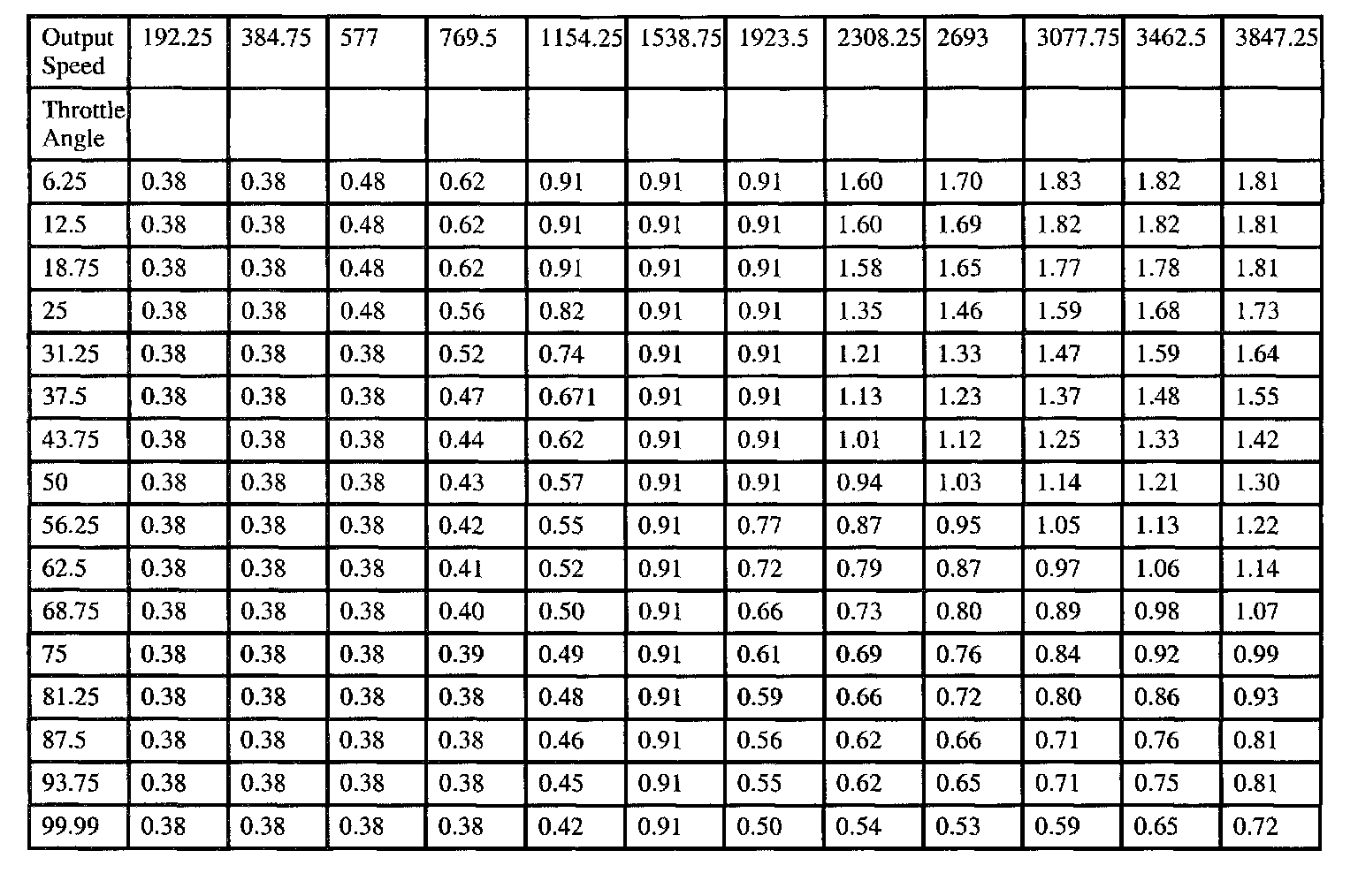
RATIO CHART STEADY
6. Repeat step 5 and compare with Ratio Chart Steady.
7. Monitor the TCC Enable Solenoid and accelerate to a chosen throttle angle. The TCC Enable Solenoid should be on at 500 RPM Transmission OSS and above.
8. Coasting down the TCC Enable Solenoid should be off at 450 RPM Transmission OSS and below.
9. Repeat steps 5-8 using different throttle angles.