Steering Column Replacement
Steering Column Replacement
Removal Procedure
1. Place the steering wheel in the straight forward position.
2. Remove the steering wheel.
3. Remove the instrument panel (I/P) lower compartment.

4. Remove the column trim covers.

5. Disconnect the head lamp/turn signal harness connector from the SIR coil module assembly.
6. Disconnect the wiper/washer harness connector from the SIR coil module assembly.
7. Disconnect the SIR coil harness connector from the SIR coil module assembly.

8. Remove the SIR coil Module assembly.

9. Disconnect the ignition lock cylinder harness connector.
10. Disconnect the ignition switch harness connector.

11. Place scribe marks on the intermediate shaft to steering column, for use during assembly.

12. Remove the intermediate shaft pinch bolt at the steering column and discard.
13. Slide the intermediate shaft off the steering column.

14. Disconnect the electric power steering (EPS) control module power feed harness connector.
15. Disconnect the EPS control module small harness connector.

16. Remove the steering column pivot bolt.
17. Remove the steering column mounting bolts.
18. Remove the column from the vehicle and place on a bench.
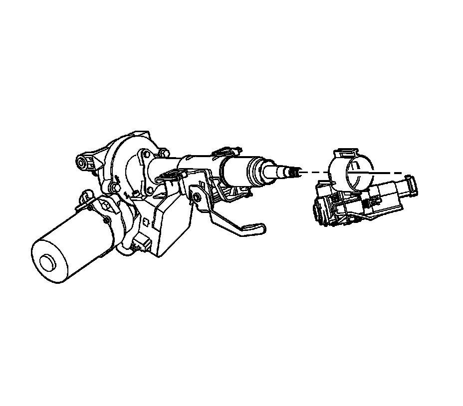
19. Remove the ignition lock cylinder case from the steering column.
Installation Procedure
1. If replacing the steering column duplicate the scribed mark placed on the old column.
2. Install the ignition lock cylinder case to the steering column.
3. Position the steering column in the vehicle.
4. Hand start the steering column mid-pivot bolt.
5. Hand start the steering column mounting bolts.
Notice: Refer to Fastener Notice.
6. Tighten the column bolts using the following order:
1. Tighten the mid-pivot bolt to 25 N.m (18 lb ft).
2. Tighten the RH column mounting bolt to 25 N.m (18 lb ft).
3. Tighten the LH column mounting bolt to 25 N.m (18 lb ft).
7. Connect the EPS control module power feed harness connector.
8. Connect the EPS control module small harness connector.
Important: For proper realignment of the steering column to intermediate shaft, use the previously scribed marks.
9. Slide the intermediate shaft onto the steering column while aligning the previously scribed marks.
10. If the steering column to intermediate shaft was not previously scribed.
11. Install a new intermediate shaft pinch bolt.
Tighten bolt to 34 N.m (25 lb ft).
12. Connect the ignition lock cylinder harness connector.
13. Connect the ignition switch harness connector.
14. Install the SIR coil module assembly.
15. Connect the SIR coil harness connector to the SIR coil module assembly.
16. Connect the wiper/washer harness connector to the SIR coil module assembly.
17. Connect the head lamp/turn signal harness connector to the SIR coil module assembly.
18. Install the upper and lower shroud.
19. Install the I/P lower compartment.
20. Install the steering wheel.