Upper Intake Manifold Replacement
Upper Intake Manifold Replacement (LCS) (3.6L Hybrid)
Upper Intake Manifold Replacement
1. Remove Fuel Injector Sight Shield. Refer to Fuel Injector Sight Shield Replacement (LY7) (Service and Repair)Fuel Injector Sight Shield Replacement (LCS) (Service and Repair).
2. Remove the air cleaner outlet duct. Refer to Air Cleaner Outlet Duct Replacement (Air Cleaner Outlet Duct Replacement).
3. Remove Drive Motor Generator Control Module Assembly. Refer to Drive Motor Generator Control Module Assembly Replacement (Drive Motor Generator Control Module Assembly Replacement).

4. Disconnect and remove the positive crankcase ventilation (PCV) tube (1) from the intake manifold and right camshaft cover.

5. Remove the evaporative (EVAP) hose from the intake manifold and EVAP solenoid.

6. Loosen the EVAP solenoid bolt.
7. Remove the EVAP solenoid (1).

8. Remove the fuel pump cover bolt (1).
9. Remove the fuel pump cover (2).

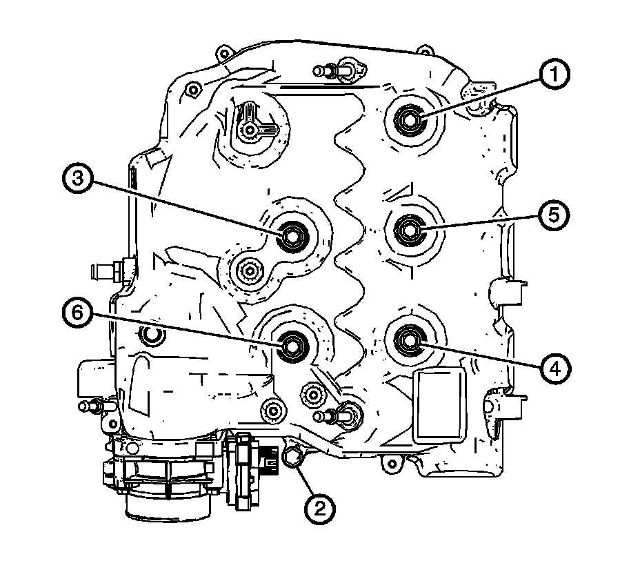
10. Remove the intake manifold bolts (1, 2).
11. Remove the intake manifold assembly (3).

12. Remove and discard the intake manifold gasket (1).
13. Discount any electrical connectors as needed.
14. Discount any hose as needed.
15. Clean and inspect the intake manifold and the sealing surfaces.
Installation Procedure
1. Install the NEW intake manifold gasket (1).
2. Install the intake manifold assembly (3).
3. Install the intake manifold bolts (1, 2).
Caution: Refer to Fastener Caution (Fastener Caution).
4. Tighten the intake manifold bolts in the sequence shown.
5. Tighten the intake manifold bolts in sequence to 23 N.m (17 lb ft).
6. Tighten the intake manifold bolts a second pass in sequence to 23 N.m (17 lb ft).
7. Install the fuel pump cover (2).
8. Install the fuel pump cover bolt (1) and tighten to 10 N.m (89 lb in).
9. Install the evaporative (EVAP) solenoid (1).
10. Tighten the EVAP solenoid bolt to 10 N.m (89 lb in).
11. Connect the EVAP hose to the upper intake manifold and EVAP solenoid.
12. Connect the positive crankcase ventilation (PCV) tube assembly (1) to the upper intake manifold and the right camshaft cover.
13. Install Drive Motor Generator Control Module Assembly. Refer to Drive Motor Generator Control Module Assembly Replacement (Drive Motor Generator Control Module Assembly Replacement).
14. Install the air cleaner outlet duct. Refer to Air Cleaner Outlet Duct Replacement (Air Cleaner Outlet Duct Replacement).
15. Connect electrical connectors as needed.
16. Install Fuel Injector Sight Shield. Refer Fuel Injector Sight Shield Replacement (LY7) (Service and Repair)Fuel Injector Sight Shield Replacement (LCS) (Service and Repair).