Pinout Values and Diagnostic Parameters
DOOR LOCK: WIRELESS DOOR LOCK CONTROL SYSTEM: TERMINALS OF ECU; 2013 MY FR-S [03/2012 -]
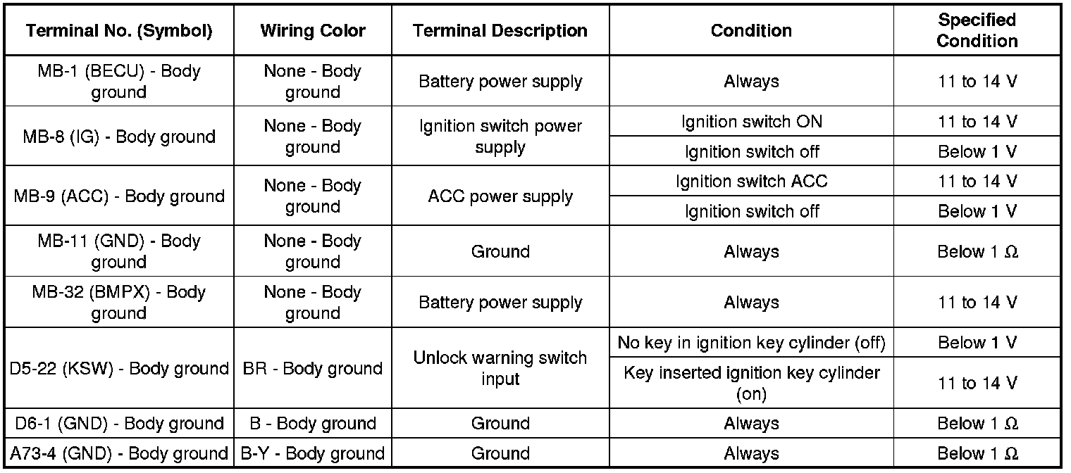
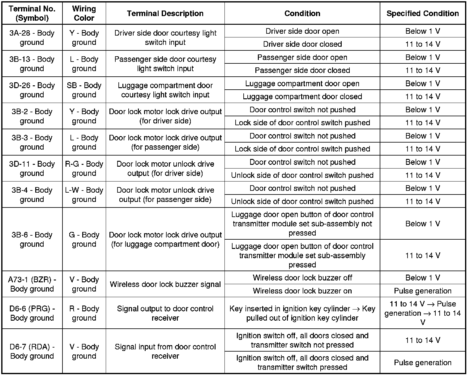
1. CHECK INSTRUMENT PANEL JUNCTION BLOCK ASSEMBLY AND MAIN BODY ECU (NETWORK GATEWAY ECU)
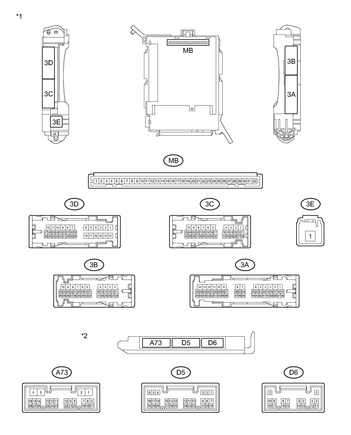

(a) Remove the main body ECU (network gateway ECU) from the instrument panel junction block assembly.
(b) Disconnect the D5, D6 and A73 main body ECU (network gateway ECU) connectors.
(c) Measure the resistance and voltage between each terminal of the wire harness side connectors and body ground.
(d) Reconnect the D5, D6 and A73 main body ECU (network gateway ECU) connectors.
(e) Install the main body ECU (network gateway ECU) to the instrument panel junction block assembly.
(f) Measure the voltage and resistance, according to the valve(s) in the table below.
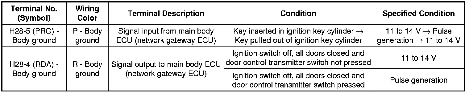
2. CHECK DOOR CONTROL RECEIVER

(a) Disconnect the H28 door control receiver connector.
(b) Measure the resistance and voltage according to the value(s) in the table below.
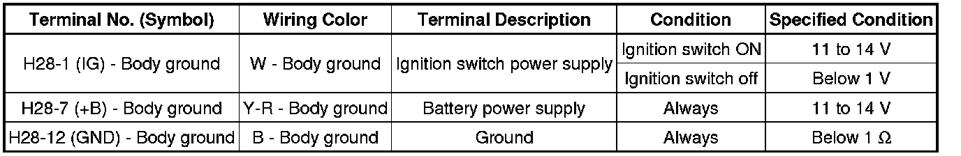
(c) Reconnect the H28 door control receiver connector.
(d) Measure the voltage according to the value(s) in the table below.