All Doors Lock/Unlock Functions Do Not Operate Via Door Control Switch
DOOR LOCK: POWER DOOR LOCK CONTROL SYSTEM: All Doors LOCK/UNLOCK Functions do not Operate Via Door Control Switch; 2013 MY FR-S [03/2012 -]
- All Doors LOCK/UNLOCK Functions do not Operate Via Door Control Switch
DESCRIPTION
The main body ECU (network gateway ECU) receives switch signals from the door control switch, activates the door lock motor on each door accordingly.
WIRING DIAGRAM

INSPECTION PROCEDURE
PROCEDURE
1. CHECK DOOR LOCK OPERATION
(a) Proceed to the next step according to the symptom listed in the table below.
Result

B -- READ VALUE USING TECHSTREAM (DOOR LOCK SW-LOCK AND DOOR LOCK SW-UNLOCK)
A -- Continue to next step.
2. READ VALUE USING TECHSTREAM (DOOR LOCK SW-LOCK AND DOOR LOCK SW-UNLOCK)
(a) Connect the Techstream to the DLC3.
(b) Turn the ignition switch to ON.
(c) Turn the Techstream on.
(d) Enter the following menus: Body Electrical / Main Body / Data List.
(e) Read the Data List according to the display on the Techstream.
Main Body
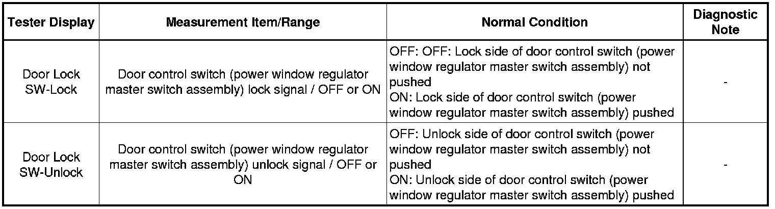
OK:
The Techstream indicates ON or OFF according to the switch operation shown in the table above.
NG -- INSPECT POWER WINDOW REGULATOR MASTER SWITCH ASSEMBLY
OK -- REPLACE MAIN BODY ECU (NETWORK GATEWAY ECU) Removal
3. INSPECT POWER WINDOW REGULATOR MASTER SWITCH ASSEMBLY
(a) Remove the power window regulator master switch assembly Removal.


(b) Measure the resistance according to the value(s) in the table below.
Standard Resistance:

NG -- REPLACE POWER WINDOW REGULATOR MASTER SWITCH ASSEMBLY Removal
OK -- Continue to next step.
4. CHECK HARNESS AND CONNECTOR (POWER WINDOW MASTER SWITCH - JUNCTION BLOCK AND BODY GROUND)
(a) Disconnect the 3A instrument panel junction block assembly connector.
(b) Disconnect the E8 power window regulator master switch assembly (door control switch) connector.
(c) Measure the resistance according to the value(s) in the table below.
Standard Resistance:

NG -- REPAIR OR REPLACE HARNESS OR CONNECTOR
OK -- Continue to next step.
5. INSPECT INSTRUMENT PANEL JUNCTION BLOCK ASSEMBLY
(a) Remove the instrument panel junction block assembly Removal.
(b) Remove the main body ECU (network gateway ECU) from the instrument panel junction block assembly.
(c) Measure the resistance according to the value(s) in the table below.


Standard Resistance:

NG -- REPLACE INSTRUMENT PANEL JUNCTION BLOCK ASSEMBLY Removal
OK -- REPLACE MAIN BODY ECU (NETWORK GATEWAY ECU) Removal
6. READ VALUE USING TECHSTREAM (DOOR LOCK SW-LOCK AND DOOR LOCK SW-UNLOCK)
(a) Connect the Techstream to the DLC3.
(b) Turn the ignition switch to ON.
(c) Turn the Techstream on.
(d) Enter the following menus: Body Electrical / Main Body / Data List.
(e) Read the Data List according to the display on the Techstream.
Main Body

OK:
The Techstream indicates ON or OFF according to the switch operation shown in the table above.
NG -- INSPECT POWER WINDOW REGULATOR SWITCH ASSEMBLY
OK -- REPLACE MAIN BODY ECU (NETWORK GATEWAY ECU) Removal
7. INSPECT POWER WINDOW REGULATOR SWITCH ASSEMBLY
(a) Remove the power window regulator switch assembly Removal.


(b) Measure the resistance according to the value(s) in the table below.
Standard Resistance:

NG -- REPLACE POWER WINDOW REGULATOR SWITCH ASSEMBLY Removal
OK -- Continue to next step.
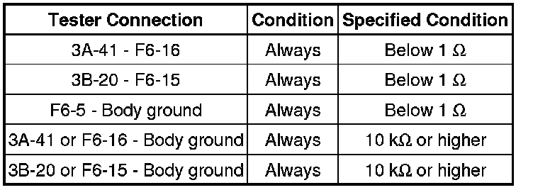
8. CHECK HARNESS AND CONNECTOR (POWER WINDOW SWITCH - JUNCTION BLOCK AND BODY GROUND)
(a) Disconnect the 3A and 3B instrument panel junction block assembly connector.
(b) Disconnect the F6 power window regulator switch assembly (door control switch) connector.
(c) Measure the resistance according to the value(s) in the table below.
Standard Resistance:
NG -- REPAIR OR REPLACE HARNESS OR CONNECTOR
OK -- Continue to next step.
9. INSPECT INSTRUMENT PANEL JUNCTION BLOCK ASSEMBLY
(a) Remove the instrument panel junction block assembly Removal.
(b) Remove the main body ECU (network gateway ECU) from the instrument panel junction block assembly.
(c) Measure the resistance according to the value(s) in the table below.


Standard Resistance:

NG -- REPLACE INSTRUMENT PANEL JUNCTION BLOCK ASSEMBLY Removal
OK -- REPLACE MAIN BODY ECU (NETWORK GATEWAY ECU) Removal