VSC OFF Indicator Light Remains On
BRAKE CONTROL / DYNAMIC CONTROL SYSTEMS: VEHICLE STABILITY CONTROL SYSTEM: VSC OFF Indicator Light Remains ON; 2013 MY FR-S [03/2012 -]
- VSC OFF Indicator Light Remains ON
DESCRIPTION
The skid control ECU (brake actuator assembly) is connected to the combination meter assembly via CAN communication.
Pressing the VSC OFF switch turns off TR(A)C and pressing and holding this switch turns off TR(A)C and VSC. If VSC is turned off, the VSC OFF indicator light will come on.
WIRING DIAGRAM

INSPECTION PROCEDURE
NOTICE:
When replacing the skid control ECU (brake actuator assembly), perform VSC sensor neutral memorization Programming and Relearning.
PROCEDURE
1. CHECK CAN COMMUNICATION SYSTEM
(a) Check if a CAN communication system DTC is output Diagnosis System.
Result:

B -- INSPECT CAN COMMUNICATION SYSTEM How to Proceed With Troubleshooting
A -- Continue to next step.
2. CHECK IF BRAKE ACTUATOR ASSEMBLY CONNECTOR IS SECURELY CONNECTED
(a) Check if the skid control ECU (brake actuator assembly) connector is securely connected.
OK:
The connector is securely connected.
NG -- CONNECT CONNECTOR TO ECU CORRECTLY
OK -- Continue to next step.
3. CHECK BATTERY
(a) Check the battery voltage.
Standard Voltage:
11 to 14 V
NG -- CHECK OR REPLACE CHARGING SYSTEM COMPONENT OR BATTERY Component Tests and General Diagnostics
OK -- Continue to next step.
4. READ VALUE USING TECHSTREAM (VSC OFF SWITCH)
(a) Connect the Techstream to the DLC3.
(b) Turn the ignition switch to ON.
(c) Select the Data List using the Techstream Data List / Active Test.
ABS/VSC/TRAC

(d) Using the Techstream, check that the switch condition displayed on the Techstream changes according to VSC OFF switch operation.
OK:
The Techstream display changes according to VSC OFF switch operation.
NG -- INSPECT VSC OFF SWITCH
OK -- Continue to next step.
5. READ VALUE USING TECHSTREAM (VSC SPORT SWITCH)
(a) Select the Data List using the Techstream Data List / Active Test.
ABS/VSC/TRAC

(b) Using the Techstream, check that the switch condition displayed on the Techstream changes according to VSC SPORT switch operation.
OK:
The Techstream display changes according to VSC SPORT switch operation.
NG -- INSPECT VSC SPORT SWITCH
OK -- Continue to next step.
6. INSPECT COMBINATION METER ASSEMBLY
(a) Perform an Active Test of the combination meter assembly (meter CPU) using the Techstream Meter / Gauge System.
(b) Check the combination meter assembly.
OK:
The VSC OFF indicator and VSC SPORT indicator lights turn on or off in accordance with the Active Test operation.
HINT
If troubleshooting has been carried out according to Problem Symptoms Table, refer back to the table and proceed to the next step before replacing parts Problem Symptoms Table.
NG -- REPLACE COMBINATION METER ASSEMBLY Removal
OK -- REPLACE BRAKE ACTUATOR ASSEMBLY Removal
7. INSPECT VSC OFF SWITCH
(a) Remove the VSC OFF switch Removal.
(b) Inspect the VSC OFF switch Testing and Inspection.
NG -- REPLACE PATTERN SELECT SWITCH ASSEMBLY Removal
OK -- Continue to next step.
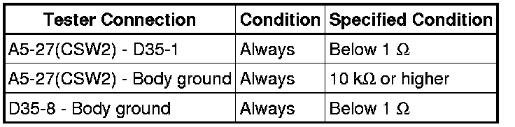
8. CHECK HARNESS AND CONNECTOR (BRAKE ACTUATOR ASSEMBLY - VSC OFF SWITCH)
(a) Disconnect the skid control ECU (brake actuator assembly) connector.
(b) Measure the resistance according to the value(s) in the table below.
Standard Resistance:

HINT
If troubleshooting has been carried out according to Problem Symptoms Table, refer back to the table and proceed to the next step before replacing parts Problem Symptoms Table.
NG -- REPAIR OR REPLACE HARNESS OR CONNECTOR
OK -- REPLACE BRAKE ACTUATOR ASSEMBLY Removal
9. INSPECT VSC SPORT SWITCH
(a) Remove the VSC SPORT switch Removal.
(b) Inspect the VSC SPORT switch Testing and Inspection.
NG -- REPLACE PATTERN SELECT SWITCH ASSEMBLY Removal
OK -- Continue to next step.
10. CHECK HARNESS AND CONNECTOR (BRAKE ACTUATOR ASSEMBLY - VSC SPORT SWITCH)
(a) Disconnect the skid control ECU (brake actuator assembly) connector.
(b) Measure the resistance according to the value(s) in the table below.
Standard Resistance:
HINT
If troubleshooting has been carried out according to Problem Symptoms Table, refer back to the table and proceed to the next step before replacing parts Problem Symptoms Table.
NG -- REPAIR OR REPLACE HARNESS OR CONNECTOR
OK -- REPLACE BRAKE ACTUATOR ASSEMBLY Removal