Cylinder Block Assembly: Testing and Inspection
FA20 ENGINE MECHANICAL: CYLINDER BLOCK: INSPECTION; 2013 MY FR-S [03/2012 -]
1. INSPECT CYLINDER BLOCK SUB-ASSEMBLY
(a) Visually check that there are no cracks, scratches or other damage.
(b) Using a dye penetrant, check the important sections for fissures.
(c) Check that there are no signs of gas leak or water leak on gasket attachment surfaces.
(d) Check the oil passages for clogging.
2. INSPECT CYLINDER BLOCK FOR WARPAGE
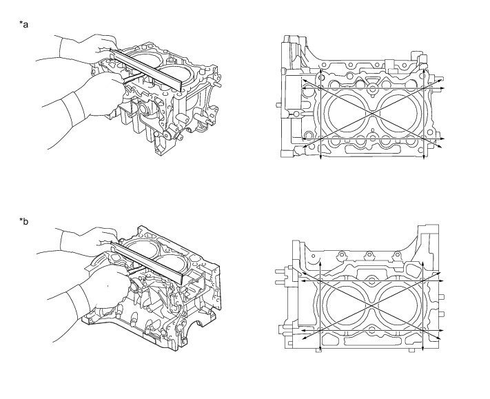
(a) Using a precision straightedge and a feeler gauge, measure the surfaces that contact the cylinder head for warpage.
Maximum warpage:
0.025 mm (0.00098 in.)
If the warpage is greater than the maximum, correct the surface by grinding it or replace the cylinder block.
HINT
Measurement should be performed at a temperature of 20°C (68°F).
Allowable minimum cylinder block height:
204.9 mm (8.067 in.)
Standard cylinder block height:
205.0 mm (8.071 in.)
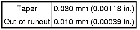
3. INSPECT CYLINDER BORE
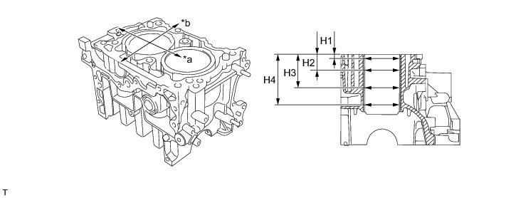
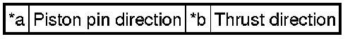
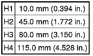
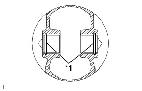
(a) Using a cylinder gauge, measure the cylinder bore diameter at positions shown in the illustration and check for taper and out-of-round.
Standard
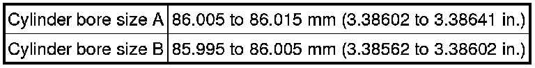
Maximum
Location
If the result is not as specified, perform boring and honing, or replace the cylinder block and piston as a set.
HINT
* Measurement should be performed at a temperature of 20°C (68°F).
* Measure the inside diameter of each cylinder bore in both the thrust and piston pin directions at the height shown in the illustration.
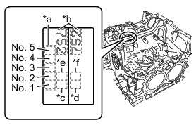
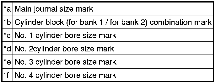
* The cylinder bore size is stamped on the upper face of the cylinder block.
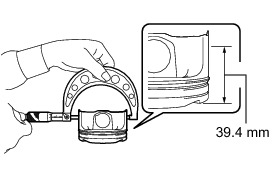
4. INSPECT PISTON DIAMETER
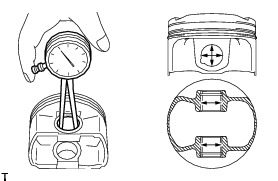
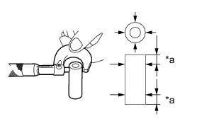
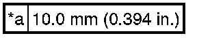
(a) Using a micrometer, measure the piston diameter at right angles to the piston pin hole, and at a point 39.4 mm (1.551 in.) from the top of the piston head.
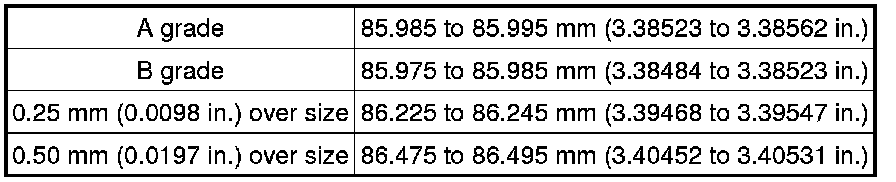
Standard
If the result is not as specified, replace the piston.
HINT
* Measurement should be performed at a temperature of 20°C (68°F).
* Measure the outer diameter of each piston in thrust direction at the height shown in the illustration.
* Standard sized pistons are classified into 2 grades, "A" and "B". These grades should be used as guide lines in selecting a standard piston diameter.
* If the piston is replaced, check the piston oil clearance, and select a suitable sized piston diameter.
5. INSPECT PISTON OIL CLEARANCE
(a) Subtract the piston diameter measurement from the cylinder bore diameter measurement.
Standard oil clearance:
0.010 to 0.030 mm (0.00039 to 0.00118 in.)
HINT
* Oil clearance = maximum cylinder bore diameter - piston diameter
* If the result is not as specified, perform boring and honing, or replace the cylinder block and piston as a set.
6. REPAIR CYLINDER LINER
(a) If any of the inside diameter, taper, out-of-round or piston oil clearance is out of standard, or if there is any damage on the cylinder liner, rebore it to replace with an oversized piston.
Allowable maximum cylinder liner diameter:
86.505 mm (3.40570 in.)
If the inside diameter of cylinder liner is more than the maximum after boring and honing, replace the cylinder block and piston as a set.
HINT
* When any of the cylinder liner needs to be rebored, all other cylinder bores must be rebored at the same time, and replaced with oversized pistons.
* Immediately after reboring, the inside diameter of the cylinder liner may differ from its actual diameter due to high temperature. Thus, when measuring the inside diameter of the cylinder liner, wait until it has cooled to the normal temperature of 20°C (68°F).
7. INSPECT PISTON WITH PIN
(a) Check the piston and piston pin for wear or cracks.
(b) Check the piston pin hole snap ring for distortion or wear.
(c) Check the piston ring groove for damage.
(d) Check the piston pin hole snap ring groove for burr.

If any burr is found, remove the burr from the groove.
(e) Check if the piston pin can be pushed into the piston pin hole with your thumb.
HINT
Measurement should be performed at a temperature of 20°C (68°F).
8. INSPECT CONNECTING ROD SMALL END BUSH
(a) Check the bushing at connecting rod small end bush for damage.
9. INSPECT PISTON PIN OIL CLEARANCE
(a) Using a caliper gauge, measure the inside diameter of the piston pin hole.
HINT
* Measurement should be performed at a temperature of 20°C (68°F).
* Measure the inside diameter of the piston pin hole at the 4 locations shown in the illustration, and take the maximum value.
* Record the measured value.
(b) Using a micrometer, measure the outer diameter of the piston pin.
HINT
* Measurement should be performed at a temperature of 20°C (68°F).
* Measure the outer diameter of the piston pin at the 4 locations shown in the illustration, and take the minimum value.
* Record the measured value.
(c) Using a caliper gauge, measure the inside diameter of bushing at connecting rod small end.
HINT
* Measurement should be performed at a temperature of 20°C (68°F).
* Measure the inside diameter of the bushing at the 4 locations shown in the illustration, and take the minimum value.
* Record the measured value.
(d) Calculate the clearance between the piston pin hole and piston pin.
Standard oil clearance:
0.004 to 0.008 mm (0.00016 to 0.00031 in.)
If the clearance between the piston pin and piston pin hole is more than the maximum, replace the piston and piston pin as a set.
HINT
Oil clearance = piston pin hole inside diameter - piston pin outer diameter
(e) Calculate the clearance between piston pin and bushing at connecting rod small end.
Standard oil clearance:
0.006 to 0.026 mm (0.00024 to 0.00102 in.)
If the clearance between the piston pin and bushing at connecting rod small end is more than the maximum, replace the connecting rod and piston pin as a set.
HINT
Oil clearance = connecting rod small end inside diameter - piston pin outer diameter
10. INSPECT PISTON RING
(a) Make sure that the piston ring is not broken or damaged.
If the piston ring is broken or damaged, replace it with a new one.
HINT
Use a piston ring of the same size as the piston to be used.
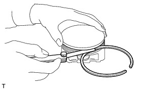
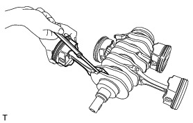
11. INSPECT PISTON RING END GAP
(a) Using a piston, push the piston ring into the cylinder.
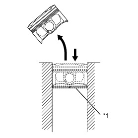
HINT
Push the piston ring into the cylinder until the entire piston is inserted into the cylinder.
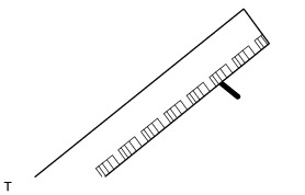
(b) Using a feeler gauge, measure the end gap.
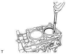
Maximum end gap
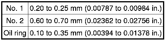
If the end gap is more than the maximum, replace the piston ring with a new one.
HINT
* Measurement should be performed at a temperature of 20°C (68°F).
* Use a piston ring of the same size as the piston to be used.
12. INSPECT RING GROOVE CLEARANCE
(a) Using a feeler gauge, measure the clearance between the piston ring and the wall of the ring groove.
Maximum clearance
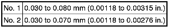
If the clearance is more than the maximum, replace the piston ring with a new one.
HINT
* Measurement should be performed at a temperature of 20°C (68°F).
* Before measuring the clearance, clean the piston ring groove and piston ring.
* Use a same sized piston ring with the piston when replacing it.
13. INSPECT CONNECTING ROD SUB-ASSEMBLY
(a) Check that the large or small end thrust surface is not damaged.
(b) Check the connecting rod assembly bearing for scar, peeling, seizure, melting or wear, etc.
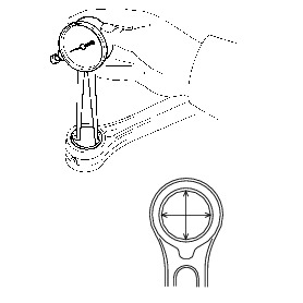
(c) Using a rod aligner and feeler gauge, check the connecting rod sub-assembly for bend.
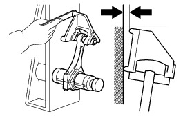
Maximum bend:
0.10 mm (0.0039 in.) per 100 mm (3.937 in.) in length
If the bend is more than the maximum, replace the connecting rod sub-assembly with a new one.
HINT
Measurement should be performed at a temperature of 20°C (68°F).
(d) Using a rod aligner and feeler gauge, check the connecting rod sub-assembly for twist.
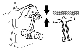
Maximum twist:
0.10 mm (0.0039 in.) per 100 mm (3.937 in.) in length
If the twist is more than the maximum, replace the connecting rod sub-assembly with a new one.
HINT
Measurement should be performed at a temperature of 20°C (68°F).
14. INSPECT CONNECTING ROD THRUST CLEARANCE
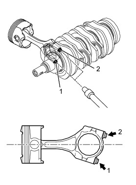
(a) Clean the connecting rod bearings and crank pins, and apply engine oil to the crank pins. [*1]
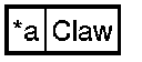
(b) Align the claw and attach the connecting rod bearing to the connecting rod.

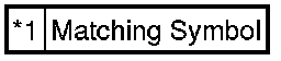
(c) Check the matching symbols and set the connecting rod, connecting rod cap and connecting rod cap bolts.

HINT
* Measurement should be performed at a temperature of 20°C (68°F).
* Each connecting rod has its own mating cap. Make sure that they are assembled correctly by checking their matching symbol.
(d) Apply engine oil to the threads of the connecting rod cap bolts.
(e) Using a "TORX" socket wrench E14, tighten the 2 connecting rod cup bolts in the order shown in the illustration.
Torque : 10 Nm (102 kgf-cm, 7 ft-lbf)
NOTICE:
* Securely hold the crankshaft during the operation.
* Be sure not to damage the crankshaft when securing it.
(f) Retighten the 2 connecting rod cup bolts in the same order as above. [*2]
Torque : 25 Nm (255 kgf-cm, 18 ft-lbf)
NOTICE:
* Securely hold the crankshaft during the operation.
* Be sure not to damage the crankshaft when securing it.
(g) In the same procedures from [*1] to [*2], install the No. 2, No. 3 and No. 4 piston with connecting rods.
(h) Using a "TORX" socket wrench E14 and an angle gauge, tighten the connecting rod cup bolts for the No. 1 to No. 4 piston with connecting rods by additional 92.5°.
NOTICE:
* Securely hold the crankshaft during the operation.
* Be sure not to damage the crankshaft when securing it.
(i) Using a feeler gauge, measure the thrust clearance for each connecting rod.
Standard thrust clearance:
0.070 to 0.330 mm (0.00276 to 0.01299 in.)
If the clearance is not within the standard, replace the connecting rod.
HINT
Measure the thrust clearance for each connecting rod at several points, and replace the connecting rod if there is uneven wear.
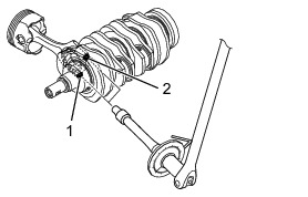
15. INSPECT CONNECTING ROD OIL CLEARANCE
(a) Clean the connecting rod bearings and crank pins, and apply engine oil to the crank pins. [*1]
(b) Attach the connecting rod bearings to the connecting rod and connecting rod cap.
(c) Lay a strip of Plastigage across the crank pin, and set the connecting rod and the connecting rod cap with the 2 connecting rod cap bolts after checking the matching symbols.

HINT
* Measurement should be performed at a temperature of 20°C (68°F).
* Each connecting rod has its own mating cap. Make sure that they are assembled correctly by checking their matching symbol.
(d) Apply engine oil to the threads of the connecting rod cap bolts.
(e) Using a "TORX" socket wrench E14, tighten the 2 connecting rod cup bolts in the order shown in the illustration.
Torque : 10 Nm (102 kgf-cm, 7 ft-lbf)
NOTICE:
* Do not turn the crankshaft.
* Securely hold the crankshaft during the operation.
* Be sure not to damage the crankshaft when securing it.
(f) Retighten the 2 connecting rod cup bolts in the same order as above. [*2]
Torque : 25 Nm (255 kgf-cm, 18 ft-lbf)
NOTICE:
* Do not turn the crankshaft.
* Securely hold the crankshaft during the operation.
* Be sure not to damage the crankshaft when securing it.
(g) In the same procedures from [*1] to [*2], install the No. 2, No. 3 and No. 4 piston with connecting rods.
(h) Using a "TORX" socket wrench E14 and an angle gauge, tighten the connecting rod cup bolts for the No. 1 to No. 4 piston with connecting rods by additional 92.5°.
(i) Remove the connecting rod cup and measure the Plastigage at its widest point.
Standard oil clearance:
0.025 to 0.055 mm (0.00098 to 0.00217 in.)
NOTICE:
Completely remove the Plastigage after the inspection.
If the oil clearance is more than the maximum, replace the bearings.
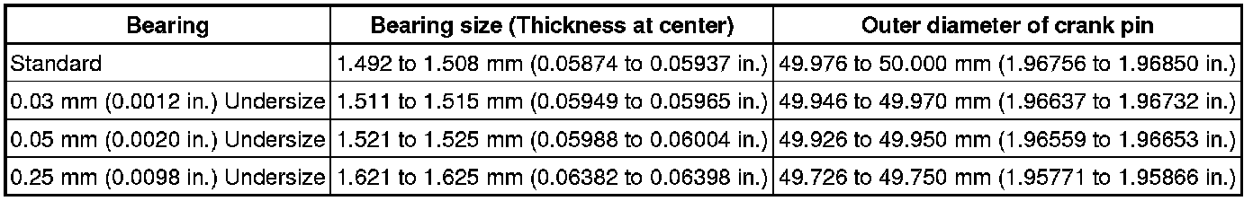
HINT
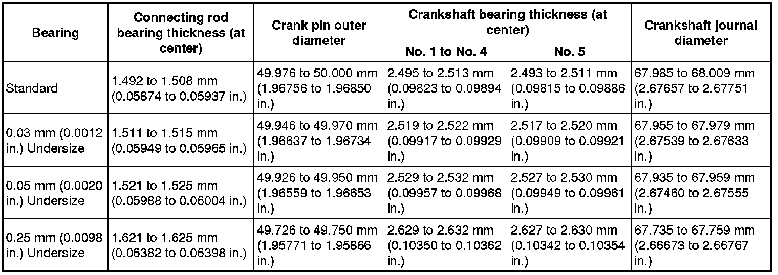
Measure the outer diameter of the crank pin using a micrometer, and select a suitable size connecting rod bearing when replacing the connecting rod bearing.
Standard
16. INSPECT CRANKSHAFT
(a) Using a dye penetrant, check the important sections for fissures.
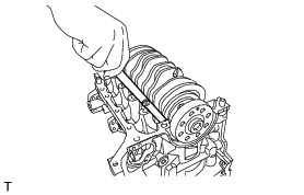
(b) Using a dial indicator, measure the circle runout at the center journal.
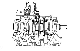
Maximum circle runout:
0.035 mm (0.00138 in.)
If the circle runout is more than the maximum, grind to correct or replace the crankshaft.
HINT
* Measurement should be performed at a temperature of 20°C (68°F).
* If a suitable V-block is not available, using just the No. 1 and No. 5 crankshaft bearings on the cylinder block, position the crankshaft on the cylinder block. Then, measure the crankshaft runout using a dial indicator.
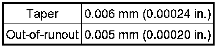
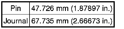
(c) Using a micrometer, check the outer diameter of the crankshaft journal and crank pin for taper and out-of-round.
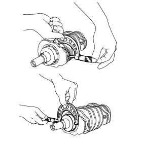
Maximum (Pin)
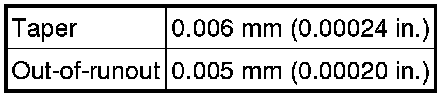
Maximum (Journal)
Allowable minimum diameter
If taper or out-of-round is more than the maximum, replace the connecting rod bearing or crankshaft bearing, and grind to correct or replace the crankshaft as required.
HINT
* Measurement should be performed at a temperature of 20°C (68°F).
* Select a suitable size connecting rod bearing or crankshaft bearing when replacing the connecting rod bearing or crankshaft bearing.
* When grinding to correct the crank journal or crank pin, finish them to the suitable dimensions as shown in the table below according to the undersize bearing to be used.
Standard

17. INSPECT CRANKSHAFT BEARING
(a) Inspect the crankshaft bearing for scar, peeling, seizure, melting or wear, etc.
18. INSPECT CRANKSHAFT THRUST CLEARANCE
(a) Using a feeler gauge, check the thrust clearance of the crankshaft at No. 5 crankshaft bearing.
Standard clearance:
0.130 to 0.308 mm (0.00512 to 0.01213 in.)
If the thrust clearance is not within the standard, replace the No. 5 crankshaft bearing.
19. INSPECT CRANKSHAFT OIL CLEARANCE
(a) Remove the seal packing left on the cylinder block.
(b) Clean the crankshaft bearings and crankshaft journals.
(c) Attach the crankshaft bearings to the cylinder block.


NOTICE:
* Be careful not to damage the matching surface of the cylinder block.
* The shapes of the No. 1 and No. 3 bearings are different from those of the No. 2 and No. 4 bearings. Be sure to attach them correctly.
(d) Place the crankshaft on the cylinder block.
(e) Lay a strip of Plastigage across each camshaft journal.
(f) Place the cylinder block (for bank 1) on the cylinder block (for bank 2).
(g) Apply engine oil to the washers and cylinder block bolt threads.
NOTICE:
To prevent engine oil from entering into the water jacket, do not apply a large amount.
(h) Using a 12 mm socket wrench, tighten the 10 bolts in the order shown in the illustration.
Torque : 35 Nm (357 kgf-cm, 26 ft-lbf)

NOTICE:
When tightening the bolts, hold the cylinder block (for bank 2) while not holding the cylinder block (for bank 1) to ensure the joint accuracy of the cylinder blocks.
(i) Using a 12 mm socket wrench, loosen the 10 bolts by 180 ° in the order shown in the illustration.

NOTICE:
When loosening the bolts, hold the cylinder block (for bank 2) while not holding the cylinder block (for bank 1) to ensure the joint accuracy of the cylinder blocks.
(j) Using a 12 mm socket wrench, tighten the 10 bolts in the order shown in the illustration.
Torque : 35 Nm (357 kgf-cm, 26 ft-lbf)
NOTICE:
When tightening the bolts, hold the cylinder block (for bank 2) while not holding the cylinder block (for bank 1) to ensure the joint accuracy of the cylinder blocks.
(k) Using a 12 mm socket wrench, loosen the 4 bolts by 180 ° in the order shown in the illustration.

NOTICE:
When loosening the bolts, hold the cylinder block (for bank 2) while not holding the cylinder block (for bank 1) to ensure the joint accuracy of the cylinder blocks.
(l) Using a 12 mm socket wrench, tighten the 4 bolts in the order shown in the illustration.
Torque : 17 Nm (173 kgf-cm, 13 ft-lbf)

NOTICE:
When tightening the bolts, hold the cylinder block (for bank 2) while not holding the cylinder block (for bank 1) to ensure the joint accuracy of the cylinder blocks.
(m) Using a 12 mm socket wrench and an angle gauge, tighten the 4 bolts by additional 60° in the order shown in the illustration.

NOTICE:
When tightening the bolts, hold the cylinder block (for bank 2) while not holding the cylinder block (for bank 1) to ensure the joint accuracy of the cylinder blocks.
(n) Using a 12 mm socket wrench, loosen the 6 bolts by 180 ° in the order shown in the illustration.

NOTICE:
When loosening the bolts, hold the cylinder block (for bank 2) while not holding the cylinder block (for bank 1) to ensure the joint accuracy of the cylinder blocks.
(o) Using a 12 mm socket wrench, tighten the 6 bolts in the order shown in the illustration.
Torque : 17 Nm (173 kgf-cm, 13 ft-lbf)

NOTICE:
When tightening the bolts, hold the cylinder block (for bank 2) while not holding the cylinder block (for bank 1) to ensure the joint accuracy of the cylinder blocks.
(p) Using a 12 mm socket wrench and an angle gauge, tighten the 6 bolts by additional 60° in the order shown in the illustration.

NOTICE:
When tightening the bolts, hold the cylinder block (for bank 2) while not holding the cylinder block (for bank 1) to ensure the joint accuracy of the cylinder blocks.
(q) Using a 12 mm socket wrench, loosen the 10 bolts in the order shown in the illustration.
(r) Remove the 10 bolts and cylinder block (for bank 1).
NOTICE:
Lift the cylinder block (for bank 1) slightly, and confirm that the crankshaft remains on the cylinder block (for bank 2). If the cylinder block (for bank 1) is lifted carelessly when separating, the crankshaft may fall off as it may have stuck to the cylinder block (for bank 1).
(s) Measure the Plastigage at its widest point.
Standard clearance:
0.013 to 0.031 mm (0.00051 to 0.00122 in.)
If the clearance is not within the standard, replace the crankshaft bearing, and grind to correct or replace the crankshaft as required.
NOTICE:
Completely remove the Plastigage after the inspection.
HINT
* Select the suitable size connecting rod bearing or crankshaft bearing when replacing the connecting rod bearing or crankshaft bearing.
* When grinding to correct the crank journal or crank pin, finish them to the suitable dimensions as shown in the table below according to the undersize bearing to be used.
Standard