Installation
FA20 ENGINE MECHANICAL: CYLINDER HEAD GASKET: INSTALLATION; 2013 MY FR-S [03/2012 -]
1. INSTALL NO. 2 CYLINDER HEAD GASKET
(a) Operate the engine stand so that the bank 2 side faces upward.
(b) Clean the bolt holes in the cylinder block (bank 2).
NOTICE:
To avoid erroneous tightening of the bolts, clean out the bolt holes sufficiently by blowing with compressed air to eliminate engine coolant, etc.
(c) Apply the seal packing to both sides of the No. 2 cylinder head gasket as shown in the illustration.
Seal packing:
Three Bond 1217G or equivalent


NOTICE:
* Clean and degrease the contact surface.
* Install the cylinder head sub-assembly LH within 5 minutes of applying the seal packing.
(d) Place the No. 2 cylinder head gasket on the cylinder block (bank 2).
2. INSTALL CYLINDER HEAD SUB-ASSEMBLY LH
(a) Clean the threads of the cylinder head bolts and apply sufficient engine oil to the washers and threads of the bolts.
(b) Mount the cylinder head sub-assembly LH on the cylinder block (bank 2).
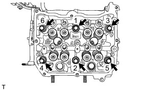
(c) Tighten the 6 cylinder head bolts in the order shown in the illustration.
Torque : 20 Nm (204 kgf-cm, 15 ft-lbf)

(d) Tighten the 6 cylinder head bolts further in the same order above.
Torque : 100 Nm (1020 kgf-cm, 74 ft-lbf)
NOTICE:
If the bolt makes a stick-slip sound during tightening, repeat the procedure from the cylinder head gasket installation after cleaning and completely drying the bolt holes and contact surfaces.
HINT
In that case, the No. 2 cylinder head gasket can be reused.
(e) Loosen the 6 cylinder head bolts by 360 ° in the order shown in the illustration.

(f) Tighten the 6 cylinder head bolts in the order shown in the illustration.
Torque : 20 Nm (204 kgf-cm, 15 ft-lbf)
(g) Tighten the 6 cylinder head bolts further in the same order above.
Torque : 42 Nm (428 kgf-cm, 31 ft-lbf)
(h) Using an angle gauge, tighten the 6 cylinder head bolts another 100 ° in the order shown in the illustration.


HINT
Temporarily install the appropriate bolt for angle gauge if necessary.
(i) Using an angle gauge, tighten the 2 cylinder head bolts another 100 ° in the order shown in the illustration.

(j) Using an angle gauge, tighten the 4 cylinder head bolts another 50 ° in the order shown in the illustration.

3. INSTALL CAMSHAFT HOUSING SUB-ASSEMBLY LH
Reassembly
4. INSTALL CYLINDER HEAD GASKET
(a) Operate the engine stand so that the bank 1 side faces upward.
(b) Clean the bolt holes in the cylinder block (bank 1).
NOTICE:
To avoid erroneous tightening of the bolts, clean out the bolt holes sufficiently by blowing with compressed air to eliminate engine coolant, etc.
(c) Apply the seal packing to both sides of the cylinder head gasket as shown in the illustration.
Seal packing:
Three Bond 1217G or equivalent


NOTICE:
* Clean and degrease the contact surface.
* Install the cylinder head sub-assembly RH within 5 minutes of applying the seal packing.
(d) Place the cylinder head gasket on the cylinder block (bank 1).
5. INSTALL CYLINDER HEAD SUB-ASSEMBLY RH
(a) Clean the threads of the cylinder head bolts and apply sufficient engine oil to the washers and threads of the bolts.
(b) Mount the cylinder head sub-assembly RH on the cylinder block (bank 1).
(c) Tighten the 6 cylinder head bolts in the order shown in the illustration.
Torque : 20 Nm (204 kgf-cm, 15 ft-lbf)
(d) Tighten the 6 cylinder head bolts further in the same order as above.
Torque : 100 Nm (1020 kgf-cm, 74 ft-lbf)
NOTICE:
If the bolt makes a stick-slip sound during tightening, repeat the procedure from the cylinder head gasket installation after cleaning and completely drying the bolt holes and contact surfaces.
HINT
In that case, the cylinder head gasket can be reused.
(e) Loosen the 6 cylinder head bolts by 360 ° in the order shown in the illustration.

(f) Tighten the 6 cylinder head bolts in the order shown in the illustration.
Torque : 20 Nm (204 kgf-cm, 15 ft-lbf)

(g) Tighten the 6 cylinder head bolts further in the same order above.
Torque : 42 Nm (428 kgf-cm, 31 ft-lbf)
(h) Using an angle gauge, tighten the 6 cylinder head bolts another 100 ° in the order shown in the illustration.


HINT
Temporarily install the appropriate bolt for angle gauge if necessary.
(i) Using an angle gauge, tighten the 2 cylinder head bolts another 100 ° in the order shown in the illustration.

(j) Using an angle gauge, tighten the 4 cylinder head bolts another 50 ° in the order shown in the illustration.

6. INSTALL CAMSHAFT HOUSING SUB-ASSEMBLY RH
Reassembly