Removal
FA20 LUBRICATION: OIL PUMP: REMOVAL; 2013 MY FR-S [03/2012 -]
1. DISCONNECT CABLE FROM NEGATIVE BATTERY TERMINAL Removal
2. DRAIN ENGINE COOLANT Service and Repair
3. REMOVE GENERATOR ASSEMBLY
Removal
4. REMOVE INJECTOR DRIVER Removal
5. REMOVE RADIATOR RESERVE TANK ASSEMBLY Removal
6. REMOVE WATER FILLER SUB-ASSEMBLY Removal
7. REMOVE EXHAUST MANIFOLD
Removal
8. DISCONNECT RADIATOR OUTLET HOSE Removal
9. DRAIN ENGINE OIL Replacement
10. REMOVE WATER PUMP PULLEY Removal
11. REMOVE CRANKSHAFT PULLEY Removal
12. REMOVE INJECTOR COVER (for Bank 1) Removal
13. DISCONNECT ENGINE WIRE
(a) Remove the 2 bolts and disconnect the 2 wire harness clamp brackets from the engine assembly.
(b) Remove the bolts and disconnect the wire harness clamp bracket from the engine assembly.
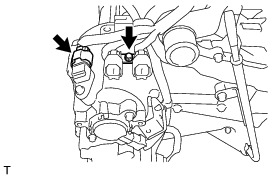
(c) Disconnect the camshaft position sensor connector.
(d) Disconnect the camshaft position sensor connector and 2 camshaft timing oil control valve connectors.

(e) Disconnect the camshaft position sensor connector and camshaft timing oil control valve connector.

(f) Disconnect the engine oil pressure switch connector and engine oil temperature connector.
(g) Disengage the clamp.
(h) Disconnect the camshaft position sensor connector and camshaft timing oil control valve connector.

14. REMOVE OIL LEVEL DIPSTICK GUIDE

(a) Remove the oil level dipstick sub-assembly.
(b) Remove the bolt and oil level dipstick guide.
(c) Remove the O-ring from the oil level dipstick guide.
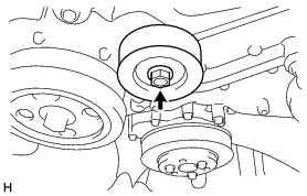
15. REMOVE NO. 2 IDLER PULLEY SUB-ASSEMBLY
(a) Remove the bolt, washer plate and No. 2 idler pulley sub-assembly.

16. REMOVE V-RIBBED BELT TENSIONER ASSEMBLY
(a) Remove the 4 bolts and V-ribbed belt tensioner assembly.

17. REMOVE NO. 1 IDLER PULLEY SUB-ASSEMBLY
(a) Remove the bolt, washer plate and No. 1 idler pulley sub-assembly.

(b) Remove the bolt, washer plate and No. 1 idler pulley sub-assembly.
18. REMOVE TIMING CHAIN OR BELT COVER OIL SEAL Removal
19. REMOVE TIMING CHAIN OR BELT COVER SUB-ASSEMBLY
(a) Remove the 32 bolts.

(b) Using a screwdriver with its tip wrapped with protective tape, remove the timing chain or belt cover sub-assembly by prying between the timing chain or belt cover sub-assembly and cylinder head or cylinder block.


NOTICE:
Be careful not to damage the contact surfaces of the cylinder head, cylinder block or chain cover.
(c) Remove the 4 O-rings.
