Part 2
FA20 ENGINE MECHANICAL: ENGINE UNIT: DISASSEMBLY; 2013 MY FR-S [03/2012 -] (Continued)
20. REMOVE WATER OUTLET
(a) Remove the 2 bolts and water outlet.

21. REMOVE THERMOSTAT
(a) Remove the thermostat.
(b) Remove the gasket from the thermostat.
NOTICE:
Be careful not to let SST slip during the work.
22. REMOVE CRANKSHAFT PULLEY
(a) Using SST, hold the crankshaft pulley and loosen the crank pulley bolt.
NOTICE:
Be careful not to let SST slip during the work.
SST : 09960-10010
09962-01000
09963-01000


(b) Remove the crankshaft pulley.
(c) Remove the O-ring and crankshaft pulley spacer.

23. REMOVE TIMING CHAIN OR BELT COVER OIL SEAL
(a) Using a screwdriver with its tip wrapped in protective tape, pry out the timing chain or belt cover oil seal.


NOTICE:
After the removal, check the crankshaft for damage. If it is damaged, smooth the surface with 400-grit sandpaper.
HINT
Tape the screwdriver tip before use.
24. REMOVE TIMING CHAIN OR BELT COVER SUB-ASSEMBLY
(a) Remove the 32 bolts.

(b) Using a screwdriver with its tip wrapped in protective tape, remove the timing chain or belt cover sub-assembly by prying between the timing chain or belt cover sub-assembly and cylinder head or cylinder block.


NOTICE:
Be careful not to damage the contact surfaces of the cylinder head, cylinder block or chain cover.
(c) Remove the 4 O-rings.

25. REMOVE CHAIN SUB-ASSEMBLY (for Bank 1)
(a) Temporarily install the crank pulley bolt to the crankshaft.
(b) Turn the crankshaft and align the alignment marks of the crankshaft timing gear or sprocket, camshaft timing intake gear assembly RH and camshaft timing exhaust gear assembly RH.
HINT
The crankshaft key faces downward at this time.


(c) Push down the chain tensioner slipper and retain the plunger by inserting a 2.5 mm (0.098 in.) diameter hexagonal wrench into the No. 1 chain tensioner assembly through the stopper plate.

(d) Remove the 2 bolts and No. 1 chain tensioner assembly.

(e) Remove the chain tensioner slipper.
(f) Using a 5 mm hexagonal wrench, remove the bolt and No. 1 chain vibration damper.

(g) Remove the chain sub- assembly (for bank 1).
NOTICE:
* With the chain sub- assembly (for bank 1) removed, the valve heads may contact each other if the camshafts are turned, causing the valve stems to bend.
* To avoid this, do not turn the intake camshaft RH and the exhaust camshaft RH more than zero-lift range (The range where camshafts can be turned lightly by hand).
HINT
Arrange the removed parts in the correct order.
26. REMOVE CHAIN SUB-ASSEMBLY (for Bank 2)
(a) Turn the crankshaft and position each alignment mark on the crankshaft timing gear or sprocket, camshaft timing intake gear assembly LH and camshaft timing exhaust gear assembly LH as shown in the illustration.


(b) Push the chain tensioner slipper and retain the plunger by inserting an approximately 1 mm (0.039 in.) diameter wire into the No. 2 chain tensioner assembly through the stopper plate.

(c) Remove the 2 bolts and No. 2 chain tensioner assembly.

(d) Remove the chain tensioner slipper.
(e) Remove the O-ring from the cylinder block.

(f) Using a 5 mm socket hexagon wrench, remove the bolt and No. 1 chain vibration damper.

(g) Remove the chain sub-assembly (for bank 2).
NOTICE:
* With the chain sub-assembly (for bank 2) removed, the valve heads may contact each other if the camshafts are turned, causing the valve stems to bend. To avoid this, do not turn the exhaust camshaft LH more than zero-lift rang (The range where the camshaft can be turned lightly by hand).
* At this time, No. 1 and No. 4 pistons are located near TDC. If the intake camshaft is turned, the valves may come into contact with the piston, causing the valve stems to bend. To avoid this, do not turn the intake camshaft LH.
HINT
Arrange the removed parts in the correct order.
27. ROTATE CRANK SHAFT AND CAMSHAFT Removal
28. REMOVE CRANKSHAFT TIMING GEAR OR SPROCKET
(a) Remove the crankshaft timing gear or sprocket.

HINT
Make sure the front-back direction and make a mark for installation if necessary.
29. REMOVE CAMSHAFT TIMING INTAKE GEAR ASSEMBLY RH Removal
30. REMOVE CAMSHAFT TIMING EXHAUST GEAR ASSEMBLY RH Removal
31. REMOVE CAMSHAFT TIMING INTAKE GEAR ASSEMBLY LH Removal
32. REMOVE CAMSHAFT TIMING EXHAUST GEAR ASSEMBLY LH Removal
33. REMOVE SPARK PLUG
(a) Using a 14 mm spark plug wrench, remove the 4 spark plugs.
34. REMOVE INJECTOR DRIVER BRACKET
(a) Remove the 2 bolts and injector driver bracket.

35. REMOVE CYLINDER HEAD COVER SUB-ASSEMBLY RH
(a) Operate the engine stand so that the bank 1 side faces upward.
(b) Remove the 8 bolts.

(c) Using a screwdriver with its tip wrapped in protective tape, remove the cylinder head cover sub-assembly RH.
NOTICE:
Do not damage the camshaft housing sub-assembly RH, cam caps and cylinder head cover sub-assembly RH.
(d) Remove the cylinder head cover gasket.
(e) Remove the 2 spark plug tube gaskets.

NOTICE:
When removing the seal packing left on the camshaft housing sub-assembly RH using a scraper, use special care not to damage the camshafts.
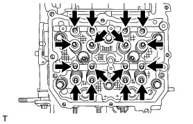
36. REMOVE CAMSHAFT HOUSING SUB-ASSEMBLY RH
NOTICE:
Do not remove the intake and exhaust camshafts first as it may cause a deformation of the cylinder head sub-assembly.
(a) Loosen the 9 bolts in the order shown in the illustration and remove them.

(b) Using a screwdriver with its tip wrapped in protective tape, remove the camshaft housing sub-assembly RH.
NOTICE:
Do not damage the cylinder head sub-assembly RH and camshaft housing sub-assembly RH.
(c) Remove the 2 O-rings and 8 No. 1 valve rocker arm sub-assemblies from the cylinder head sub-assembly.

HINT
Arrange the removed parts in the correct order.
(d) Remove the 8 valve adjusting shims and 8 roller rocker arm pivots from the cylinder head sub-assembly.
HINT
Arrange the removed parts in the correct order.
37. REMOVE CYLINDER HEAD SUB-ASSEMBLY RH Removal
38. REMOVE CYLINDER HEAD GASKET Removal