Part 3
FA20 ENGINE MECHANICAL: ENGINE UNIT: DISASSEMBLY; 2013 MY FR-S [03/2012 -] (Continued)
39. REMOVE CYLINDER HEAD COVER SUB-ASSEMBLY LH
(a) Operate the engine stand so that the bank 2 side faces upward.
(b) Remove the 8 bolts.

(c) Using a screwdriver with its tip wrapped in protective tape, remove the cylinder head cover sub-assembly LH.
NOTICE:
Do not damage the camshaft housing sub-assembly LH, cam caps and cylinder head cover sub-assembly LH.
(d) Remove the cylinder head cover gasket.
(e) Remove the 2 spark plug tube gaskets.

NOTICE:
When removing the seal packing left on the camshaft housing sub-assembly LH using a scraper, use special care not to damage the camshafts.
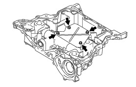
40. REMOVE CAMSHAFT HOUSING SUB-ASSEMBLY LH
NOTICE:
Do not remove the intake and exhaust camshafts first as it may cause a deformation of the camshaft housing sub-assembly LH.
(a) Loosen the 9 bolts in the order shown in the illustration and remove them.

(b) Using a screwdriver with its tip wrapped in protective tape, remove the camshaft housing sub-assembly LH.
NOTICE:
Do not damage the cylinder head sub-assembly LH and camshaft housing sub-assembly LH.
(c) Remove the 2 O-rings and 8 No. 1 valve rocker arm sub-assemblies from the cylinder head sub-assembly LH.

HINT
Arrange the removed parts in the correct order.
(d) Remove the 8 valve adjusting shims and 8 roller rocker arm pivots from the cylinder head sub-assembly LH.

HINT
Arrange the removed parts in the correct order.
41. REMOVE CYLINDER HEAD SUB-ASSEMBLY LH Removal
42. REMOVE NO. 2 CYLINDER HEAD GASKET Removal
43. REMOVE NO. 2 ENGINE HANGER

(a) Remove the 2 bolts and No. 2 engine hanger from the cylinder block (for bank 1).
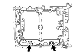
44. REMOVE NO. 2 OIL PAN SUB-ASSEMBLY
(a) Remove the drain plug and gasket.
(b) Remove the 11 bolts.
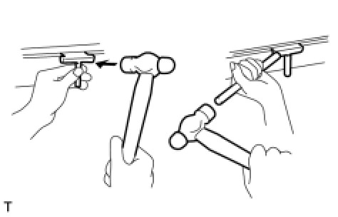
(c) Using an oil pan seal cutter, remove the No. 2 oil pan sub-assembly.
NOTICE:
Do not damage the contact surface and flange part of the No. 2 oil pan sub-assembly.
(d) Remove the 2 seal rings from the No. 2 oil pan sub-assembly.

45. REMOVE OIL STRAINER SUB-ASSEMBLY
(a) Remove the 2 bolts and oil strainer sub-assembly.

(b) Remove the O-ring.
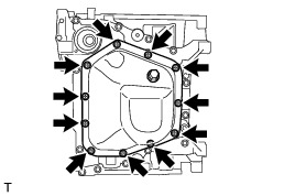
46. REMOVE OIL PAN SUB-ASSEMBLY
(a) Remove the 13 bolts.

(b) Using a screwdriver with its tip wrapped in protective tape, remove the oil pan sub-assembly.
NOTICE:
Do not damage the cylinder block and oil pan sub-assembly.
(c) Remove the 3 O-rings from the cylinder block.

(d) Remove the 4 bolts and baffle plate from the oil pan sub-assembly.
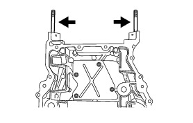
(e) Remove the 2 stud bolts from the oil pan sub-assembly.
47. REMOVE CAMSHAFT BEARING CAP (for Bank 1) Removal
48. REMOVE CAMSHAFT (for Bank 1) Removal
49. REMOVE OIL CONTROL VALVE FILTER (for Bank 1)
(a) Remove the 2 oil control valve filters from the camshaft housing sub-assembly RH.

50. REMOVE OIL SPACER RH
(a) Remove the 2 bolts and oil spacer RH.

51. REMOVE CAMSHAFT OIL FEED PIPE SUB-ASSEMBLY (for Automatic Transmission)
(a) Remove the 2 union bolts, the bolt, camshaft oil feed pipe sub-assembly and 2 gaskets from the camshaft housing sub-assembly RH.

52. REMOVE HOLE PLUG (for Manual Transmission)
(a) Remove the hole plug and gasket from the camshaft housing sub-assembly RH.

53. REMOVE CAMSHAFT BEARING CAP (for Bank 2) Removal
54. REMOVE CAMSHAFT (for Bank 2) Removal
55. REMOVE OIL CONTROL VALVE FILTER (for Bank 2)
(a) Remove the 2 oil control valve filters from the camshaft housing sub-assembly LH.

56. REMOVE OIL SPACER LH
(a) Remove the 2 bolts and oil spacer LH.