Part 1
FA20 ENGINE MECHANICAL: ENGINE UNIT: REASSEMBLY; 2013 MY FR-S [03/2012 -]
1. INSTALL OIL SPACER LH
(a) Install the oil spacer LH with the 2 bolts.
Torque : 6.4 Nm (65 kgf-cm, 57 in-lbf)
2. INSTALL OIL CONTROL VALVE FILTER (for Bank 2)
(a) Install 2 new oil control valve filters to the camshaft housing sub-assembly LH as shown in the illustration.

3. INSTALL CAMSHAFT (for Bank 2) Installation
4. INSTALL CAMSHAFT CAP (for Bank 2) Installation
5. INSTALL HOLE PLUG (for Manual Transmission)
(a) Install a new gasket and the hole plug to the camshaft housing sub-assembly RH.

Torque : 25 Nm (255 kgf-cm, 18 ft-lbf)
6. INSTALL CAMSHAFT OIL FEED PIPE SUB-ASSEMBLY (for Automatic Transmission)
(a) Temporarily install 2 new gaskets and the camshaft oil feed pipe sub-assembly with the bolt and 2 union bolts.
(b) Tighten the 2 union bolts to the specified torque.

Torque : 31 Nm (316 kgf-cm, 23 ft-lbf)
(c) Tighten the bolt to the specified torque.
Torque : 6.4 Nm (65 kgf-cm, 57 in-lbf)
7. INSTALL OIL SPACER RH
(a) Install the oil spacer RH with the 2 bolts.

Torque : 6.4 Nm (65 kgf-cm, 57 in-lbf)
8. INSTALL OIL CONTROL VALVE FILTER (for Bank 1)
(a) Install 2 new oil control valve filters to the camshaft housing sub-assembly RH as shown in the illustration.


9. INSTALL CAMSHAFT (for Bank 1) Installation
10. INSTALL CAMSHAFT CAP (for Bank 1) Installation
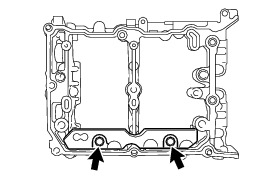
11. INSTALL OIL PAN SUB-ASSEMBLY
(a) Install the 2 stud bolts to the oil pan sub-assembly.

Torque : 10 Nm (102 kgf-cm, 7 ft-lbf)
Standard height (A):
70.0 mm (2.756 in.)
(b) Install the baffle plate to the oil pan sub-assembly with the 4 bolts.
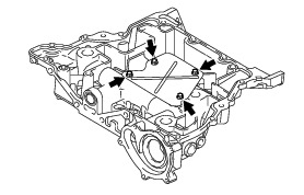
Torque : 6.4 Nm (65 kgf-cm, 57 in-lbf)
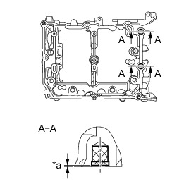
(c) Apply seal packing in a continuous line as shown in the illustration.

Seal packing:
Three Bond 1217G or equivalent
NOTICE:
* Clean and degrease the contact surface.
* Install the oil pan sub-assembly within 5 minutes of applying seal packing.
* Apply seal packing 1.5 mm (0.0591 in.) away from the outer side of the chamfer edge. However, it is allowed to apply the seal packing on the chamfer around the bolt hole.
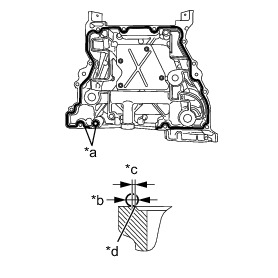
(d) Install 3 new O-rings to the cylinder block.

(e) Tighten the 13 bolts in the order shown in the illustration to install the oil pan sub-assembly to the cylinder block.
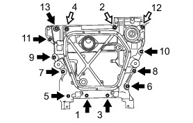

Length of bolt A:
25.0 mm (0.984 in.)
Length of bolt B:
75.0 mm (2.953 in.)
HINT
After tightening the bolts, if the seal packing is squeezed out onto the seal surface of the chain cover, completely remove it.
12. INSTALL OIL STRAINER SUB-ASSEMBLY

(a) Install a new O-ring.
(b) Install the oil strainer sub-assembly to the oil pan sub-assembly with the 2 bolts.
Torque : 6.4 Nm (65 kgf-cm, 57 in-lbf)
13. INSTALL NO. 2 OIL PAN SUB-ASSEMBLY
(a) Install 2 new oil pan seal rings to the No. 2 oil pan sub-assembly.

(b) Apply seal packing in a continuous line as shown in the illustration.


Seal packing:
Three Bond 1217G or equivalent
NOTICE:
* Clean and degrease the contact surface.
* Install the No. 2 oil pan sub-assembly within 5 minutes of applying seal packing.
(c) Tighten the 11 bolts in the order shown in the illustration to install the No. 2 oil pan sub-assembly.

Torque : 6.4 Nm (65 kgf-cm, 57 in-lbf)
(d) Install a new gasket and the drain plug.
Torque : 39 Nm (400 kgf-cm, 29 ft-lbf)
14. INSTALL NO. 2 ENGINE HANGER
(a) Install the No. 2 engine hanger to the cylinder block (for bank 1) with the 2 bolts.

Torque : 21 Nm (214 kgf-cm, 16 ft-lbf)
15. INSTALL NO. 2 CYLINDER HEAD GASKET Installation
16. INSTALL CYLINDER HEAD SUB-ASSEMBLY LH Installation
17. INSTALL CAMSHAFT HOUSING SUB-ASSEMBLY LH
(a) Apply engine oil to the 8 valve adjusting shims and 8 roller rocker arm pivots, and then install them to the cylinder head sub-assembly LH.

(b) Apply engine oil to 2 new O-rings and the 8 No. 1 valve rocker arm sub-assemblies, and then install them to the cylinder head sub-assembly LH.

(c) Apply seal packing in a continuous line as shown in the illustration.
Seal packing:
Three Bond 1217G or equivalent


NOTICE:
* Clean and degrease the contact surface.
* Do not apply excessive seal packing.
* Install the camshaft housing sub-assembly LH within 5 minutes of applying seal packing.
* After tightening the bolts, if the seal packing is squeezed out onto the seal surface of the chain cover, completely remove it.
(d) Tighten the 9 bolts in the order shown in the illustration to install the camshaft housing sub-assembly LH.
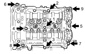
Torque : 18 Nm (184 kgf-cm, 13 ft-lbf)
HINT
Set the intake camshaft LH and the exhaust camshaft LH to the zero-lift position.

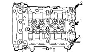
(e) Loosen the 3 bolts by 180° in the order shown in the illustration.

(f) Tighten the 3 bolts in the order shown in the illustration.

Torque : 18 Nm (184 kgf-cm, 13 ft-lbf)
(g) Loosen the 3 bolts by 180° in the order shown in the illustration.

(h) Tighten the 3 bolts in the order shown in the illustration.

Torque : 18 Nm (184 kgf-cm, 13 ft-lbf)
(i) Loosen the 3 bolts by 180° in the order shown in the illustration.

(j) Tighten the 3 bolts in the order shown in the illustration.
Torque : 18 Nm (184 kgf-cm, 13 ft-lbf)
HINT
After tightening the bolts, if the seal packing is squeezed out onto the seal surface of the chain cover, completely remove it.
18. INSPECT VALVE CLEARANCE (for Bank 2)
NOTICE:
With the chain sub-assembly (for bank 2) removed, valve heads may contact each other if the camshafts are turned, causing the valve stems to bend. To avoid this, do not turn the intake camshaft LH and exhaust camshaft LH more than the zero-lift rang (The range where the camshafts can be turned lightly by hand).
(a) Using a feeler gauge, check the valve clearance between the cam base circle and the roller surface of the No. 1 valve rocker arm sub-assembly.

Standard valve clearance (cold):
0.10 to 0.16 mm (0.0039 to 0.0063 in.) for intake
0.21 to 0.27 mm (0.0083 to 0.0106 in.) for exhaust
HINT
* Set the intake camshaft LH and the exhaust camshaft LH to the zero-lift position.
* If the clearance is not as specified, take notes of the value in order to adjust the valve clearance later on.
19. ADJUST VALVE CLEARANCE (for Bank 2)
(a) Remove the camshaft housing sub-assembly LH.
(b) Remove the No. 1 valve rocker arm sub-assemblies.
(c) Remove the valve adjusting shims.
(d) Using a micrometer, measure the thickness of the valve adjusting shims.

(e) Calculate the thickness of the valve adjusting shim so that the valve clearance comes within the specified values.
Intake side:
A = B + (C - 0.13 mm (0.0051 in.) x 1.54
Exhaust side:
A = B + (C - 0.24 mm (0.0094 in.) x 1.69
A:
Required valve adjusting shim thickness
B:
Removed valve adjusting shim thickness
C:
Measured valve clearance
(f) Apply engine oil to the inner face of the valve adjusting shims and install them to the valves.
NOTICE:
Check if the shims can be rotated smoothly on the valves.
(g) Install the No. 1 valve rocker arm sub-assemblies.
(h) Install the camshaft housing sub-assembly LH.
(i) Check that the No. 1 valve rocker arm sub-assemblies are correctly installed.
20. INSTALL CYLINDER HEAD COVER SUB-ASSEMBLY LH
(a) Apply a light layer of engine oil to 2 new spark plug tube gaskets and install them to the spark plug tubes as shown in the illustration.


(b) Install a new cylinder head cover gasket to the cylinder head cover sub-assembly LH.
(c) Apply seal packing to the mating surface of cylinder head cover sub-assembly LH as shown in the illustration.


Seal packing:
Three Bond 1217G or equivalent

(d) Tighten the 8 bolts in the order shown in the illustration and install the cylinder head cover sub-assembly LH.

Torque : 6.4 Nm (65 kgf-cm, 57 in-lbf)