Part 2
FA20 ENGINE MECHANICAL: ENGINE UNIT: REASSEMBLY; 2013 MY FR-S [03/2012 -] (Continued)
21. INSTALL CYLINDER HEAD GASKET Installation
22. INSTALL CYLINDER HEAD SUB-ASSEMBLY RH Installation
23. INSTALL CAMSHAFT HOUSING SUB-ASSEMBLY RH
(a) Apply engine oil to the 8 valve adjusting shims and 8 roller rocker arm pivots, and then install them to the cylinder head sub-assembly.
(b) Apply engine oil to 2 new O-rings and the 8 No. 1 valve rocker arm sub-assemblies, and then install them to the cylinder head sub-assembly.

(c) Apply seal packing in a continuous line as shown in the illustration.
Seal packing:
Three Bond 1217G or equivalent


NOTICE:
* Clean and degrease the contact surface.
* Do not apply excessive seal packing.
* Install the camshaft housing sub-assembly RH within 5 minutes of applying seal packing.
* After tightening the bolts, if the seal packing is squeezed out onto the seal surface of the chain cover, completely remove it.
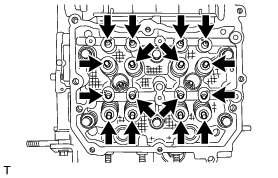
(d) Tighten the 9 bolts in the order shown in the illustration to install the camshaft housing sub-assembly RH.

Torque : 18 Nm (184 kgf-cm, 13 ft-lbf)
HINT
Set the intake camshaft RH and the exhaust camshaft RH to the zero-lift position.
(e) Loosen the 3 bolts by 180° in the order shown in the illustration.

(f) Tighten the 3 bolts in the order shown in the illustration.

Torque : 18 Nm (184 kgf-cm, 13 ft-lbf)
(g) Loosen the 3 bolts by 180° in the order shown in the illustration.

(h) Tighten the 3 bolts in the order shown in the illustration.

Torque : 18 Nm (184 kgf-cm, 13 ft-lbf)
(i) Loosen the 3 bolts by 180° in the order shown in the illustration.

(j) Tighten the 3 bolts in the order shown in the illustration.

Torque : 18 Nm (184 kgf-cm, 13 ft-lbf)
HINT
After tightening the bolts, if the seal packing is squeezed out onto the seal surface of the chain cover, completely remove it.
24. INSPECT VALVE CLEARANCE (for Bank 1)
NOTICE:
With the chain sub-assembly (for bank 1) removed, valve heads may contact each other if the camshafts are turned, causing the valve stems to bend. To avoid this, do not turn the intake camshaft RH and exhaust camshaft RH more than the zero-lift rang (The range where the camshafts can be turned lightly by hand).
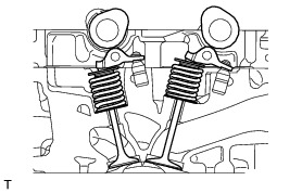
(a) Using a feeler gauge, check the valve clearance between the cam base circle and the roller surface of the No. 1 valve rocker arm sub-assembly.

Standard valve clearance (cold):
0.10 to 0.16 mm (0.0039 to 0.0063 in.) for intake
0.21 to 0.27 mm (0.0083 to 0.0106 in.) for exhaust
HINT
* Set the intake camshaft RH and the exhaust camshaft RH to the zero-lift position.
* If the clearance is not as specified, take notes of the value in order to adjust the valve clearance later on.
25. ADJUST VALVE CLEARANCE (for Bank 1)
(a) Remove the camshaft housing sub-assembly RH.
(b) Remove the No. 1 valve rocker arm sub-assemblies.
(c) Remove the valve adjusting shims.
(d) Using a micrometer, measure the thickness of the valve adjusting shims.

(e) Calculate the thickness of the valve adjusting shim so that the valve clearance comes within the specified values.
Intake side:
A = B + (C - 0.13 mm (0.0051 in.) x 1.54
Exhaust side:
A = B + (C - 0.24 mm (0.0094 in.) x 1.69
A:
Required valve adjusting shim thickness
B:
Removed valve adjusting shim thickness
C:
Measured valve clearance
(f) Apply engine oil to the inner face of the valve adjusting shims and install them to the valves.
NOTICE:
Check if the shims can be rotated smoothly on the valves.
(g) Install the No. 1 valve rocker arm sub-assemblies.
(h) Install the camshaft housing sub-assembly RH.
(i) Check that the No. 1 valve rocker arm sub-assemblies are correctly installed.
26. INSTALL CYLINDER HEAD COVER SUB-ASSEMBLY RH
(a) Apply a light layer of engine oil to 2 new spark plug tube gaskets and install them to the spark plug tubes as shown in the illustration.


(b) Install a new cylinder head cover gasket to the cylinder head cover sub-assembly RH.
(c) Apply seal packing to the mating surface of cylinder head cover sub-assembly RH as shown in the illustration.


Seal packing:
Three Bond 1217G or equivalent

(d) Tighten the 8 bolts in the order shown in the illustration and install the cylinder head cover sub-assembly RH.

Torque : 6.4 Nm (65 kgf-cm, 57 in-lbf)
27. INSTALL INJECTOR DRIVER BRACKET
(a) Install the injector driver bracket with the 2 bolts.

Torque : 6.4 Nm (65 kgf-cm, 57 in-lbf)
28. INSTALL SPARK PLUG
(a) Using a 14 mm spark plug wrench, install the 4 spark plugs.
Torque : 17 Nm (173 kgf-cm, 13 ft-lbf)
29. INSTALL CAMSHAFT TIMING EXHAUST GEAR ASSEMBLY LH Installation
30. INSTALL CAMSHAFT TIMING INTAKE GEAR ASSEMBLY LH Installation
31. INSTALL CAMSHAFT TIMING EXHAUST GEAR ASSEMBLY RH Installation
32. INSTALL CAMSHAFT TIMING INTAKE GEAR ASSEMBLY RH Installation
33. INSTALL CRANKSHAFT TIMING GEAR OR SPROCKET
(a) Install the crankshaft timing gear or sprocket.

HINT
The crankshaft timing gear or sprocket should be installed as it was before.
34. INSTALL CHAIN SUB-ASSEMBLY (for Bank 2)
NOTICE:
Do not allow any foreign matter to adhere or to enter into the component parts during installation.
HINT
Apply engine oil to all component parts of the chain sub-assembly.
(a) Temporarily install the crank pulley bolt to the crankshaft.
(b) Move the link plate in the direction of the arrow in the illustration to press in the plunger.


(c) Insert an approximately 1 mm (0.0394 in.) diameter wire or the like into the chain tensioner assembly through the stopper pin hole, and hold the plunger.


HINT
If the stopper pin hole on the link plate and the stopper pin hole on the chain tensioner assembly are not aligned, check that the first notch of the plunger rack is engaged with the stopper tooth. If not engaged, retract the plunger a little so that the first notch of the plunger rack is engaged with the stopper tooth.
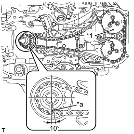
(d) Check that the crankshaft timing gear or sprocket is located at the position shown in the illustration. If not, turn the crankshaft to align the crankshaft timing gear or sprocket alignment mark as shown in the illustration.


NOTICE:
Make sure to perform this operation to prevent the valves and pistons from contacting each other.
(e) Using SST, turn the camshaft timing intake gear assembly LH and align the alignment mark as shown in the illustration.


SST : 09960-10010
09962-01000
09963-00700
NOTICE:
Do not turn the exhaust camshaft LH. If the exhaust camshaft LH is turned, valve heads may come into contact with each other, causing the valve stems to bend.
(f) Remove the crank pulley bolt from the crankshaft.
(g) Temporarily install the crankshaft pulley spacer and crankshaft pulley to the crankshaft with the crank pulley bolt.
HINT
Put a mark on the crankshaft pulley to mark the position of the crankshaft timing gear key.
(h) Using SST, turn the crankshaft counterclockwise by 200° and align the crankshaft key as shown in the illustration.


SST : 09960-10010
09962-01000
09963-01000
NOTICE:
Never turn the crankshaft clockwise because the valves may come into contact with the piston. Turning the crankshaft clockwise is only allowed when adjusting the key position precisely.
(i) Remove the crank pulley bolt, crankshaft pulley and crankshaft pulley spacer.
(j) Align the alignment mark on the camshaft timing exhaust gear assembly LH as shown in the illustration.


NOTICE:
To avoid damaging the valves, do not turn the camshaft timing exhaust gear assembly LH more than the zero-lift range (The range where camshaft timing exhaust gear assembly LH can be turned lightly by hand).
(k) Align the chain mark plate (blue) with the alignment mark on the crankshaft timing gear or sprocket.


(l) Align the chain mark plate (pink) with the timing mark on the camshaft timing intake gear assembly LH.
(m) Align the chain mark plate (pink) with the timing mark on the camshaft timing exhaust gear assembly LH.
(n) Using a 5 mm hexagon socket wrench, install the No. 1 chain vibration damper with the bolt.
Torque : 6.4 Nm (65 kgf-cm, 57 in-lbf)
HINT
Apply engine oil to the bolt before install it.
(o) Install a new O-ring to the cylinder block (for bank 2).

(p) Install the chain tensioner slipper.

(q) Install the No. 2 chain tensioner assembly with the 2 bolts.
Torque : 6.4 Nm (65 kgf-cm, 57 in-lbf)
(r) Check that the chain is correctly installed.


(1) Chain mark plate (blue) is aligned with the alignment mark on the crankshaft timing gear or sprocket.
(2) Chain mark plate (pink) is aligned with the timing mark on the camshaft timing intake gear assembly LH.
(3) Chain mark plate (pink) is aligned with the timing mark on the camshaft timing exhaust gear assembly LH.
(s) Pull out the wire or the like from the No. 2 chain tensioner assembly.
(t) Temporarily install the crank pulley bolt to the crankshaft.
(u) Turn the crankshaft clockwise, and make sure that there are no abnormal conditions.
NOTICE:
Be sure to perform this confirmation.
35. INSTALL CHAIN SUB-ASSEMBLY (for Bank 1)
NOTICE:
Do not allow any foreign matter to adhere or to enter into the component parts during installation.
HINT
Apply engine oil to all component parts of the chain sub-assembly.
(a) Move the link plate in the direction of the arrow in the illustration to press in the plunger.


(b) Insert a 2.5 mm (0.098 in.) diameter hexagon wrench into the No. 1 chain tensioner assembly through the stopper pin hole, and hold the plunger.


HINT
If the stopper pin hole on the link plate and the stopper pin hole on the chain tensioner assembly are not aligned, check that the first notch of the plunger rack is engaged with the stopper tooth. If not engaged, retract the plunger a little so that the first notch of the plunger rack is engaged with the stopper tooth.
(c) Turn the crankshaft and align the alignment marks of the crankshaft timing gear or sprocket, camshaft timing intake gear assembly LH and camshaft timing exhaust gear assembly LH as shown in the illustration.

HINT
When the marks are aligned as shown in the illustration, crankshaft key faces directly underneath.
(d) Align the alignment marks of the camshaft timing intake gear assembly RH and camshaft timing exhaust gear assembly RH as shown in the illustration.


NOTICE:
To avoid damaging the valves, do not turn the camshaft timing intake gear assembly RH and camshaft timing exhaust gear assembly RH more than the zero-lift range (The range where the camshafts can be turned lightly by hand).
(e) Align the chain mark plate (blue) with the alignment mark on the crankshaft timing gear or sprocket.


(f) Align the chain mark plate (pink) with the timing mark on the camshaft timing intake gear assembly RH.
(g) Align the chain mark plate (pink) with the timing mark on the camshaft timing exhaust gear assembly RH.
(h) Using a 5 mm hexagon socket wrench, install the No. 1 chain vibration damper with the bolt.
Torque : 6.4 Nm (65 kgf-cm, 57 in-lbf)
HINT
Apply engine oil to the bolt before install it.
(i) Install the chain tensioner slipper.

(j) Install the No. 1 chain tensioner assembly with the 2 bolts.
Torque : 6.4 Nm (65 kgf-cm, 57 in-lbf)
(k) Check that the chain is correctly installed.


(1) Chain mark plate (blue) is aligned with the alignment mark on the crankshaft timing gear or sprocket.
(2) Chain mark plate (pink) is aligned with the timing mark on the camshaft timing intake gear assembly RH.
(3) Chain mark plate (pink) is aligned with the timing mark on the camshaft timing exhaust gear assembly RH.
(l) Pull out the hexagon wrench from the No. 1 chain tensioner assembly.
(m) Turn the crankshaft clockwise, and make sure that there are no abnormal conditions.
NOTICE:
Be sure to perform this confirmation.
(n) Remove the crank pulley bolt.
36. INSTALL TIMING CHAIN OR BELT COVER SUB-ASSEMBLY
(a) Apply a light layer of engine oil to 4 new O-rings and attach them to the engine.
(b) Clean and degrease the contact surface.
(c) If there are gaps at positions shown in the illustration, fill up with seal packing.
Seal packing:
Three Bond 1217G or equivalent

(d) Apply seal packing in a continuous line as shown in the illustration.
Seal packing:
Three Bond 1217G or equivalent

NOTICE:
* Clean and degrease the contact surface.
* Install the chain cover within 5 minutes and tighten the bolts within 15 minutes of applying seal packing.
* Do not add engine oil within 30 minutes of installation.
* Do not start the engine within 30 minutes of installation.
(e) Temporarily install the timing chain or belt cover sub-assembly with the 32 bolts.
(f) Securely tighten the 32 bolts in the order as shown in the illustration.


Bolt A and B - Torque : 10 Nm (102 kgf-cm, 7 ft-lbf)
Bolt C and D - Torque : 25 Nm (255 kgf-cm, 18 ft-lbf)
Bolt Length:

37. INSTALL TIMING CHAIN COVER OIL SEAL
(a) Apply engine oil to a new oil seal lip.

NOTICE:
* Keep the lip free from foreign matter.
* Do not apply engine oil to the dust seal section.
(b) Using SST and a hammer, tap in the new oil seal until its surface is flush with the timing chain or belt cover sub-assembly edge.
SST : 09223-22010
NOTICE:
* Do not tap the oil seal at an angle.
* Do not deform the oil seal.
HINT
Alternatively, the tapping depth of the timing chain cover oil seal can be 0 to -1.0 mm (0 to -0.0394 in.) from the timing chain cover end surface.
38. INSTALL CRANKSHAFT PULLEY
(a) Install the crankshaft pulley spacer.
(b) Install a new O-ring to the crankshaft pulley spacer.
(c) Install the crankshaft pulley while aligning the knock hole of the pulley with the knock pin on the crankshaft pulley spacer.
(d) Apply engine oil to threads and seat sections of the crank pulley bolt.
(e) Using SST, hold the crankshaft pulley and tighten the crank pulley bolt.


NOTICE:
Be careful not to let SST slip during the work.
SST : 09960-10010
09962-01000
09963-01000
Torque : 20 Nm (204 kgf-cm, 15 ft-lbf)
(f) Using a marker, draw the reference line (A) on the crank pulley bolt and also the reference line (B) on the crank pulley according to the line engraved around the crank pulley bolt head as shown in the illustration.
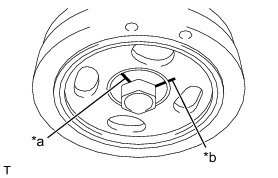

HINT
There are carved lines on the crank pulley bolt head every 90°.
(g) Using SST, hold the crankshaft pulley, and tighten the crank pulley bolt by 90° until the reference lines A and B are aligned.
NOTICE:
Be careful not to let SST slip during the work.
SST : 09960-10010
09962-01000
09963-01000

39. INSTALL THERMOSTAT
(a) Attach a new gasket to the thermostat.
40. INSTALL WATER OUTLET
(a) Install the thermostat and water outlet with the 2 bolts.

Torque : 6.4 Nm (65 kgf-cm, 57 in-lbf)