Part 3
FA20 ENGINE MECHANICAL: ENGINE UNIT: REASSEMBLY; 2013 MY FR-S [03/2012 -] (Continued)
41. INSTALL ENGINE WATER PUMP ASSEMBLY
(a) Install a new gasket and the water pump assembly with the 5 bolts.

Torque : 6.4 Nm (65 kgf-cm, 57 in-lbf)
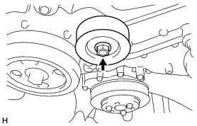
42. INSTALL WATER PUMP PULLEY
(a) Temporarily install the water pump pulley with the 3 bolts.
(b) Using SST, hold the water pump pulley.

SST : 09960-10010
09962-01000
09963-00700
(c) Securely tighten the 3 bolts.
NOTICE:
Be careful not to let SST slip during the work.
Torque : 14 Nm (143 kgf-cm, 10 ft-lbf)
43. INSTALL NO. 1 IDLER PULLEY SUB-ASSEMBLY
(a) Install the idler pulley cover and No. 1 idler pulley sub-assembly with the bolt.
Torque : 36 Nm (367 kgf-cm, 27 ft-lbf)
44. INSTALL NO. 1 IDLER PULLEY SUB-ASSEMBLY
(a) Install the idler pulley cover and No. 1 idler pulley sub-assembly with the bolt.

Torque : 36 Nm (367 kgf-cm, 27 ft-lbf)
45. INSTALL PCV VALVE SUB-ASSEMBLY
(a) Apply adhesive to 2 or 3 threads of the PCV valve sub-assembly.


Adhesive:
Three Bond 1141G or equivalent
(b) Using a 19 mm deep socket wrench, install the PCV valve sub-assembly.

Torque : 23 Nm (235 kgf-cm, 17 ft-lbf)
46. INSTALL WATER INLET PIPE
(a) Attach 2 new O-rings to the cylinder block.

(b) Install the water inlet pipe with the 4 bolts.

Torque : 6.4 Nm (65 kgf-cm, 57 in-lbf)
(c) Connect the No. 3 water by-pass hose with the clamp.
47. INSTALL REAR CYLINDER HEAD PLATE (for Manual Transmission)
(a) Apply seal packing in a continuous line as shown in the illustration.
Seal packing:
Three Bond 1217G or equivalent


NOTICE:
* Clean and degrease the contact surface.
* Install the rear cylinder head plate within 5 minutes of applying seal packing.
(b) Install the rear cylinder head plate with the 3 bolts.

Torque : 16 Nm (163 kgf-cm, 12 ft-lbf)
48. INSTALL VACUUM PUMP ASSEMBLY (for Automatic Transmission) Testing and Inspection
49. INSTALL PCV HOSE CONNECTOR
(a) Connect the No. 2 water by-pass hose to the PCV hose connector and water inlet pipe with the clips.

(b) Install the PCV hose connector with the 3 bolts.
Torque : 6.4 Nm (65 kgf-cm, 57 in-lbf)
50. INSTALL ENGINE OIL PRESSURE SWITCH ASSEMBLY
(a) Clean and degrease the threads of the engine oil pressure switch assembly.
(b) Apply adhesive 1324 to the threads of the engine oil pressure switch assembly.

Adhesive:
Toyota Genuine Adhesive 1324, Three Bond 1324 or equivalent
NOTICE:
Keep the oil hole free from adhesive.
(c) Using a 24 mm deep socket wrench, install the engine oil pressure switch assembly.


Torque : 18 Nm (184 kgf-cm, 13 ft-lbf)
NOTICE:
Do not start the engine for at least 1 hour after installation.
51. INSTALL TEMPERATURE SENSOR
(a) Attach a new gasket to the temperature sensor.
(b) Using a 19 mm deep socket wrench, install the temperature sensor.


Torque : 18 Nm (184 kgf-cm, 13 ft-lbf)
52. INSTALL CAMSHAFT TIMING OIL CONTROL VALVE
(a) Install the back-up ring to the camshaft timing oil control valve (for exhaust side of bank 2).


(b) Install a new O-ring to the camshaft timing oil control valve (for exhaust side of bank 2).
(c) Apply a light coat of engine oil to the O-ring.
(d) Install the camshaft timing oil control valve (for exhaust side of bank 2) with the 2 bolts.
Torque : 6.4 Nm (65 kgf-cm, 57 in-lbf)

(e) Install the back-up ring to the camshaft timing oil control valve (for intake side of bank 2).
(f) Install a new O-ring to the camshaft timing oil control valve (for intake side of bank 2).
(g) Apply a light coat of engine oil to the O-ring.
(h) Install the camshaft timing oil control valve (for intake side of bank 2) with the 2 bolts.
Torque : 6.4 Nm (65 kgf-cm, 57 in-lbf)

(i) Install the back-up ring to the camshaft timing oil control valve (for exhaust side of bank 1).
(j) Install a new O-ring to the camshaft timing oil control valve (for exhaust side of bank 1).
(k) Apply a light coat of engine oil to the O-ring.
(l) Install the camshaft timing oil control valve (for exhaust side of bank 1) with the 2 bolts.
Torque : 6.4 Nm (65 kgf-cm, 57 in-lbf)

(m) Install the back-up ring to the camshaft timing oil control valve (for intake side of bank 1).
(n) Install a new O-ring to the camshaft timing oil control valve (for intake side of bank 1).
(o) Apply a light coat of engine oil to the O-ring.
(p) Install the camshaft timing oil control valve (for intake side of bank 1) with the 2 bolts.
Torque : 6.4 Nm (65 kgf-cm, 57 in-lbf)

53. INSTALL VVT SENSOR
(a) Install a new O-ring to the VVT sensor (for exhaust side of bank 2).
(b) Apply a light coat of engine oil to the O-ring.
(c) Install the VVT sensor (for exhaust side of bank 2) with the bolt.
Torque : 6.4 Nm (65 kgf-cm, 57 in-lbf)

(d) Install a new O-ring to the VVT sensor (for intake side of bank 2).
(e) Apply a light coat of engine oil to the O-ring.
(f) Install the VVT sensor (for intake side of bank 2) with the bolt.
Torque : 6.4 Nm (65 kgf-cm, 57 in-lbf)

(g) Install a new O-ring to the VVT sensor (for exhaust side of bank 1).
(h) Apply a light coat of engine oil to the O-ring.
(i) Install the VVT sensor (for exhaust side of bank 1) with the bolt.
Torque : 6.4 Nm (65 kgf-cm, 57 in-lbf)

(j) Install a new O-ring to the VVT sensor (for intake side of bank 1).
(k) Apply a light coat of engine oil to the O-ring.
(l) Install the VVT sensor (for intake side of bank 1) with the bolt.
Torque : 6.4 Nm (65 kgf-cm, 57 in-lbf)

54. INSTALL CRANK POSITION SENSOR
(a) Install the crank position sensor with the bolt.
Torque : 6.4 Nm (65 kgf-cm, 57 in-lbf)

55. INSTALL KNOCK CONTROL SENSOR
(a) Install the 2 knock control sensors onto the cylinder block with the 2 bolts as shown in the illustration.
Torque : 24 Nm (245 kgf-cm, 18 ft-lbf)


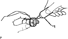
56. INSTALL E.F.I. WATER TEMPERATURE SENSOR
(a) Using a 19 mm union nut wrench, install a new gasket and the E.F.I. water temperature sensor.

Torque : 18 Nm (184 kgf-cm, 13 ft-lbf)
NOTICE:
Use the formula to calculate special torque values for situations where a union nut wrench is combined with a torque wrench Service Precautions.
57. INSTALL OIL FILTER UNION
(a) Using a 24 mm deep socket wrench, install the oil filter union.

Torque : 45 Nm (459 kgf-cm, 33 ft-lbf)
58. INSTALL OIL FILTER SUB-ASSEMBLY
(a) Apply engine oil to the installation surface of the oil filter sub-assembly.
(b) Using SST, install the oil filter sub-assembly.

SST : 09228-22020
Torque : 14 Nm (143 kgf-cm, 10 ft-lbf)
59. INSTALL OIL FILLER CAP ASSEMBLY
(a) Install the oil filler cap assembly.