Heating and Air Conditioning: Description and Operation
HEATING / AIR CONDITIONING: AIR CONDITIONING SYSTEM: SYSTEM DIAGRAM; 2013 MY FR-S [03/2012 -]
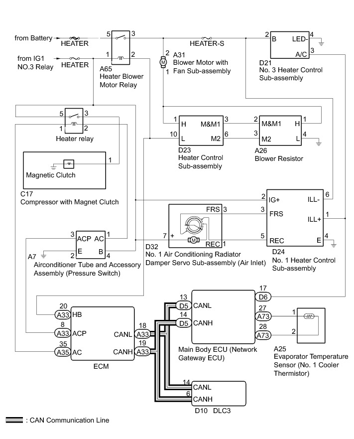
Communication Table

HEATING / AIR CONDITIONING: AIR CONDITIONING SYSTEM: SYSTEM DESCRIPTION; 2013 MY FR-S [03/2012 -]
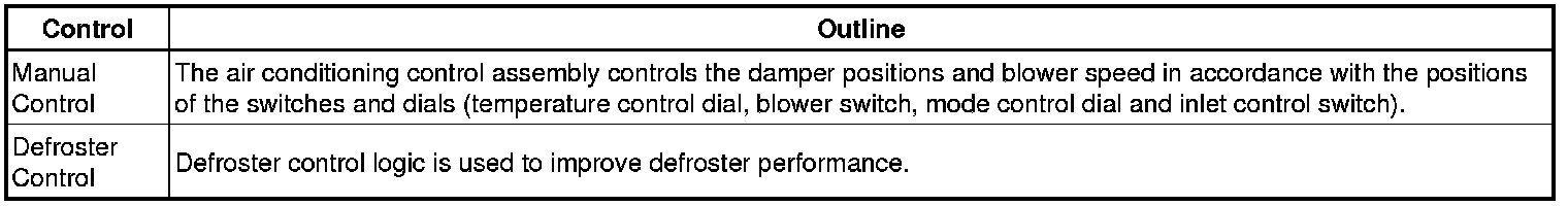
1. GENERAL
(a) The air conditioning system has the following controls.
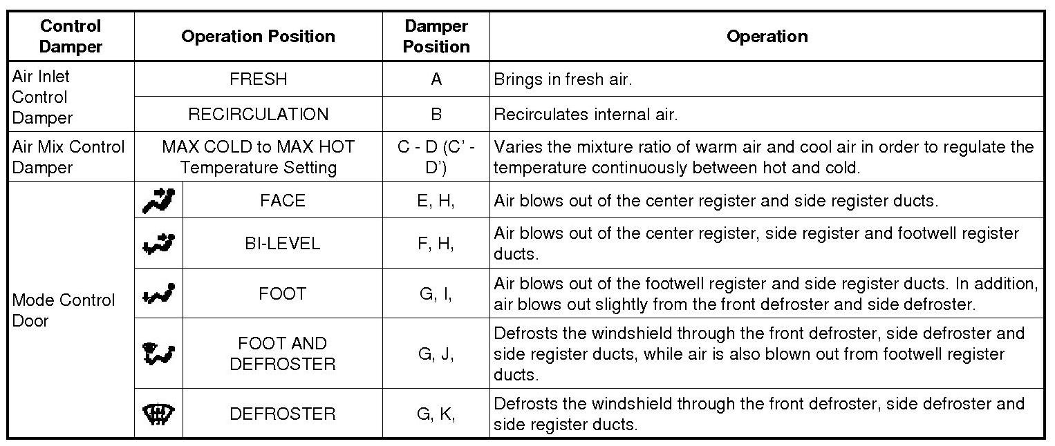
2. MODE POSITION AND DAMPER OPERATION
(a) Mode Position and Damper Operation
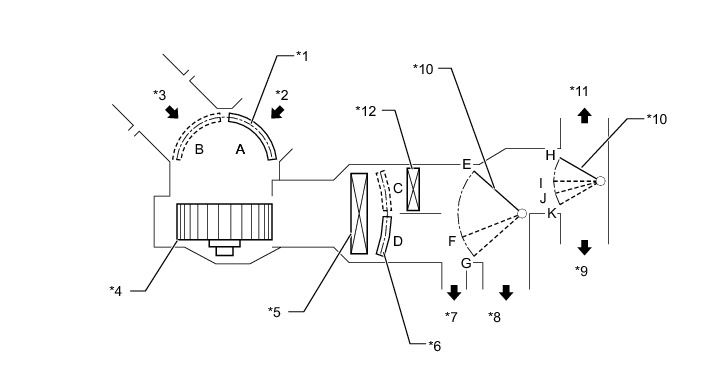
Functions of Main Dampers:
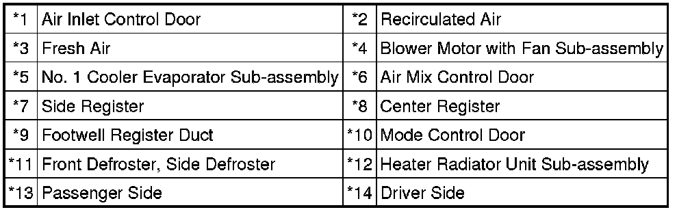
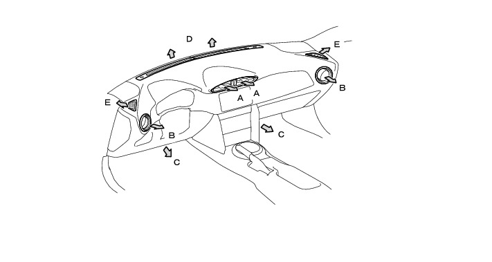
3. AIR OUTLETS AND AIRFLOW VOLUME
(a) Air Outlets and Airflow Volume
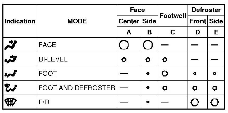
* The size of each circle o indicates the ratio of airflow volume.
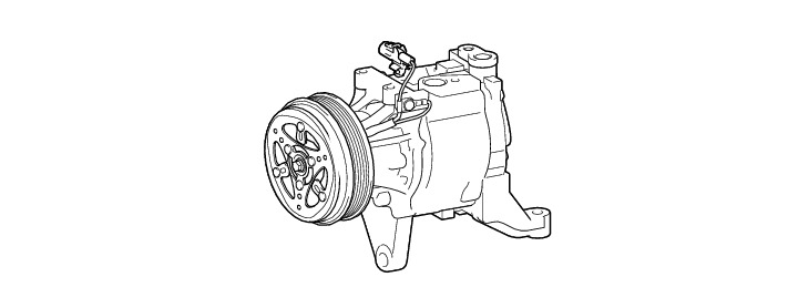
4. COMPRESSOR
(a) General:
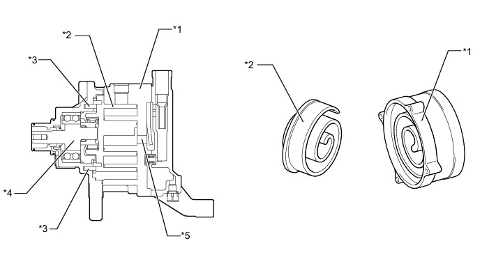
(1) A compact and high performance scroll compressor with separator has been adopted.
(2) The scroll compressor with oil separator consists of a spirally wound fixed scroll and rotating scroll that from a pair, and oil separator, and a magnetic clutch.
The fixed scroll is integrated with the housing. Because the rotation of the shaft causes the rotating scroll to revolve while maintaining the same posture, the volume of the space that is partitioned by both scrolls varies to perform the suction, compression, and the discharge of the refrigerant gas.
A pin is attached behind the rotating scroll to prevent the autorotation of the rotating scroll, allowing it only to revolve.
Locating the suction port directly above the scrolls enables direct suction, thus realizing improved suction efficiency.
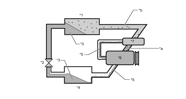
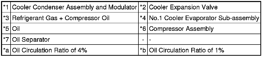
Containing a built-in oil separator, this compressor is able to separate the compressor oil that is intermixed with the refrigerant and circulates in the refrigeration cycle, thus realizing a reduction in the oil circulation rate.
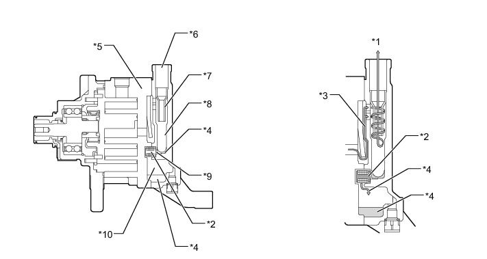
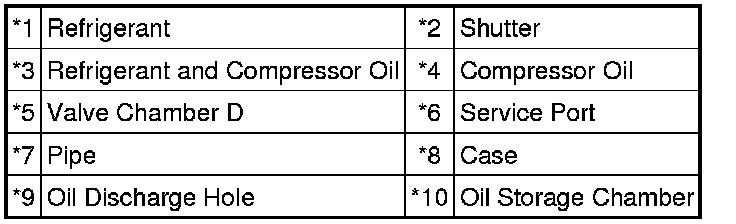
(3) A CS (Centrifugal with Shutter) type oil separator has been adopted to reduce the circulation rate of the compressor oil that is intermixed with the refrigerant and circulates in the refrigeration cycle.
This oil separator is provided with a cylindrical pipe in the separator case, enabling the refrigerant gas that has been discharged through the discharge gas inlet to be separated into refrigerant gas and oil through centrifugal force, and minimizing the outflow of the oil to the discharge service port. As a result, the oil circulation rate has been reduced and makes energy savings possible.
(b) Compressor with Magnet Clutch Operation
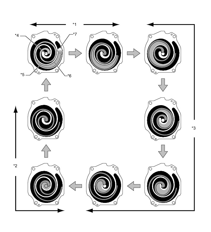
(1) As the capacity of the compression chamber, which is created between the rotating scroll and the fixed scroll, increases in accordance with the revolution of the rotating scroll, refrigerant gas is drawn in from the intake port.
(2) From the state at which the suction process has been completed, as the revolution of the rotating scroll advances further, the capacity of the compression chamber decreases gradually. Consequently, the refrigerant gas that has been drawn in becomes compressed gradually and is sent to the center of the fixed scroll. The compression of the refrigerant gas is completed when the rotating scroll completes approximately 2 revolutions.
(3) When the compression of the refrigerant gas is completed and the refrigerant pressure becomes high, the refrigerant gas discharges through the discharge port located in the center of the fixed scroll by pushing the discharge valve.
(4) The refrigerant gas that is discharged from the discharge port flows by rotating around the cylindrical pipe in the oil separator. At this time, the centrifugal force that is created during the rotation separates the refrigerant gas and the compressor oil due to the difference in their specific gravity. The refrigerant gas with the lighter specific gravity passes through the inside of the pipe and travels from the discharge service port to the outside of the compressor. The compressor oil with the heavier specific gravity is discharged through the oil discharge hole in the shutter and is stored in the oil storage chamber. Then, the compressor oil is fed again into the compressor and circulates inside the compressor.
5. EVAPORATOR TEMPERATURE SENSOR (NO. 1 COOLER THERMISTOR)
The evaporator temperature sensor (No. 1 cooler thermistor) detects the temperature of the cooled air immediately past the evaporator in the form of resistance changes, and outputs this data to the main body ECU (network gateway ECU).
6. Air Conditioning Pressure Switch (Airconditioner Tube Assembly)
The air conditioning pressure switch (airconditioner tube assembly) uses refrigerant pressure to output an on/off signal to the ECM to control the compressor with magnet clutch.