IG Signal Circuit
LIGHTING (INT): LIGHTING SYSTEM: IG Signal Circuit; 2013 MY FR-S [03/2012 -]
- IG Signal Circuit
DESCRIPTION
This circuit detects the ignition switch ON or off condition, and sends it to the main body ECU (network gateway ECU).
WIRING DIAGRAM

INSPECTION PROCEDURE
NOTICE:
Inspect the fuses for circuits related to this system before performing the following inspection procedure.
PROCEDURE
1. READ VALUE USING TECHSTREAM
(a) Connect the Techstream to the DLC3.
(b) Turn the ignition switch to ON.
(c) Turn the Techstream on.
(d) Enter the following menus: Body Electrical / Main Body / Data List.
(e) Read the display on the Techstream.
OK:
Normal conditions listed above are displayed.
Main Body

NG -- CHECK HARNESS AND CONNECTOR (INSTRUMENT PANEL JUNCTION BLOCK ASSEMBLY - BATTERY AND BODY GROUND)
OK -- PROCEED TO NEXT SUSPECTED AREA SHOWN IN PROBLEM SYMPTOMS TABLE Interior Lighting System
2. CHECK HARNESS AND CONNECTOR (INSTRUMENT PANEL JUNCTION BLOCK ASSEMBLY - BATTERY AND BODY GROUND)
(a) Disconnect the 3A and 3E instrument panel junction block assembly connectors.
(b) Measure the voltage according to the value(s) in the table below.

Standard Voltage:

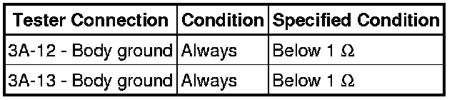
(c) Measure the resistance according to the value(s) in the table below.
Standard Resistance:
NG -- REPAIR OR REPLACE HARNESS OR CONNECTOR
OK -- Continue to next step.
3. INSPECT INSTRUMENT PANEL JUNCTION BLOCK ASSEMBLY (IG1 NO. 1 RELAY)
(a) Remove the instrument panel junction block assembly Removal.
(b) Remove the main body ECU (network gateway ECU) from the instrument panel junction block assembly.
(c) Measure the resistance according to the value(s) in the table below.


Standard Resistance:

NG -- REPLACE INSTRUMENT PANEL JUNCTION BLOCK ASSEMBLY Removal
OK -- REPLACE MAIN BODY ECU (NETWORK GATEWAY ECU) Removal