Pinout Values and Diagnostic Parameters
FA20 ENGINE CONTROL: SFI SYSTEM: TERMINALS OF ECM; 2013 MY FR-S [03/2012 -]

HINT
The standard voltage between each pair of the ECM terminals is shown in the table below. The appropriate conditions for checking each pair of the terminals are also indicated. The result of checks should be compared with the standard voltage for that pair of the terminals, and displayed in the "Specified Condition" column. The illustration above can be used as a reference to identify the ECM terminal locations.


* *1: for Automatic Transmission
* *2: for Manual Transmission
1. WAVEFORM 1

CAN Communication Signal

HINT
The waveform varies depending on the CAN communication signal.
2. WAVEFORM 2

CAN Communication Signal

HINT
The waveform varies depending on the CAN communication signal.
3. WAVEFORM 3

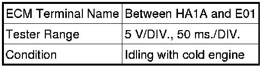
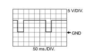
Air Fuel Ratio Sensor Heater
4. WAVEFORM 4

Injector for Direct Injection No. 1 (to No. 4) Injection Signal

HINT
The wavelength becomes shorter as the engine speed increases.
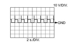
5. WAVEFORM 5

Fuel Pump for High Pressure (Spill Valve)

6. WAVEFORM 6

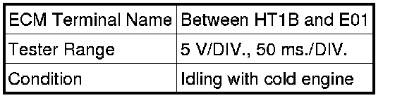
Crankshaft Position Sensor and VVT Sensor for Exhaust Camshaft

HINT
The wavelength becomes shorter as the engine speed increases.
7. WAVEFORM 7

Crankshaft Position Sensor and VVT Sensor for Intake Camshaft

HINT
The wavelength becomes shorter as the engine speed increases.
8. WAVEFORM 8

Engine Speed Signal

HINT
The wavelength becomes shorter as the vehicle speed increases.
9. WAVEFORM 9

Fuel Pump Control

10. WAVEFORM 10

Throttle Actuator

11. WAVEFORM 11

Camshaft Timing Oil Control Valve (OCV)
12. WAVEFORM 12
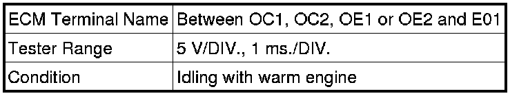
Heated Oxygen Sensor
13. WAVEFORM 13

Ignition Coil (Ignition Signal)

14. WAVEFORM 14
Purge Valve

15. WAVEFORM 15

Injector for Port Injection No. 1 (to No. 4) Injection Signal

HINT
The wavelength becomes shorter as the engine speed increases.