Removal
FA20 FUEL: FUEL PUMP: REMOVAL; 2013 MY FR-S [03/2012 -]
1. DISCHARGE FUEL SYSTEM PRESSURE
Service Precautions
2. DRAIN FUEL
(a) If the fuel gauge reads 2/3 or more, carry out the following procedure to drain fuel.
CAUTION:
After running, the engine will be very hot, so take care to avoid burns.
NOTICE:
* Be sure not to scatter any fuel.
* In some cases, there may be fuel in the fuel filler pipe section. Use a gasoline-capable pump or a gasoline-capable hose with a diameter of 10 mm (0.3937 in.) or less, to drain fuel from the fuel filler pipe section.
(1) Remove the center exhaust pipe assembly.
(2) Remove the tail exhaust pipe assembly.
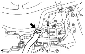
(3) Loosen the hose clamp bolt and disconnect the fuel tank to filler pipe hose.
NOTICE:
Be sure not to scatter any fuel.
(4) Place a metal container below the vehicle, and use a gasoline-capable hose with a diameter of 10 mm or less to drain fuel from the opening of fuel tank assembly to filler pipe hose.
NOTICE:
* Be sure not to scatter any fuel.
* Static electricity could possibly ignite gasoline, so be sure to use earthed metal containers.
(5) Connect the fuel tank to filler pipe hose to the fuel tank filler pipe sub-assembly with the clamp.
Torque : 2.0 Nm (20 kgf-cm, 18 in-lbf)
3. DISCONNECT CABLE FROM NEGATIVE BATTERY TERMINAL Removal
4. REMOVE SEPARATE TYPE REAR SEAT CUSHION ASSEMBLY LH Removal
5. REMOVE NO. 2 REAR FLOOR SERVICE HOLE COVER
(a) Remove the No. 2 rear floor service hole cover.

(b) Disconnect the fuel suction tube assembly with pump and gauge connector.

6. REMOVE FUEL SUCTION TUBE ASSEMBLY WITH PUMP AND GAUGE
(a) Disconnect the fuel tank main tube Service Precautions.

(b) Disengage the clamp and separate the fuel tank main tube from the fuel tank assembly.

(c) Remove the fuel pump gauge retainer.
(1) Temporarily install SST to the fuel pump gauge retainer.

SST : 09808-14030
09808-01010
09808-01020
09808-01030
09808-01050
SST : 09808-01071


NOTICE:
Do not apply a claw of SST at the marked part.
HINT
* Be sure to use SST (claws) as shown in the illustration.
* Engage SST (claws) securely with the fuel pump gauge retainer ribs to secure SST.
(2) While securely pressing SST (claws) against the fuel pump gauge retainer ribs, install the 4 bolts.
(3) Install SST (handle).
(4) Lightly press down on SST to prevent it from separating from the fuel pump gauge retainer. While pressing SST, rotate the handle slowly to loosen the fuel pump gauge retainer.

NOTICE:
* Do not use any tools other than those specified in this operation. Damage to the fuel pump gauge retainer or fuel tank may result.
* Do not press down on SST excessively as this may make the fuel pump gauge retainer hard to rotate and may damage components.
* Make sure to rotate SST (handle) horizontally. If SST (handle) is rotated at an angle, SST may come off.
* If SST comes off of the fuel pump gauge retainer, loosen SST (bolts) and reinstall SST.
(5) Disconnect the fuel tank vent hose sub-assembly Service Precautions.

(6) Remove the fuel suction tube assembly with pump and gauge from the fuel tank assembly.
NOTICE:
* Do not pull the fuel return vent tube sub-assembly forcibly when disconnecting the fuel return vent tube sub-assembly.
* Be careful not to bend the arm of the fuel sender gauge assembly.
* Do not rotate the fuel suction tube assembly inside the fuel tank assembly, as doing so may bend the fuel sender gauge arm section.
* Be sure not to spill the fuel remaining in the fuel suction tube assembly on the exterior of the fuel tank assembly or interior of the vehicle.
(7) Remove the gasket from the fuel tank assembly.