Installation
FA20 FUEL: FUEL TANK: INSTALLATION; 2013 MY FR-S [03/2012 -]
1. INSTALL NO. 1 FUEL TANK CUSHION
(a) Install 10 new No. 1 fuel tank cushions to the fuel tank assembly.
2. INSTALL NO. 2 FUEL TANK MAIN TUBE SUB-ASSEMBLY
(a) Install the fuel filter to the No. 2 fuel tank main tube sub-assembly.
(b) Install the No. 2 fuel tank main tube sub-assembly to the fuel tank assembly.
3. INSTALL FUEL TANK TO FILLER PIPE HOSE
(a) Install the fuel tank to filler pipe hose to the fuel tank assembly with the clamp.
(b) Tighten the hose clamp bolt.
Torque : 2.0 Nm (20 kgf-cm, 18 in-lbf)
4. INSTALL FUEL TANK ASSEMBLY
(a) Inspect the fuel tank cover.
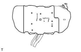
HINT
The fuel tank cover is used as a base when attaching the fuel tank assembly, so inspect for any deformation, cracking, or other damage. If any faults are found, replace with a new one.
(b) Hold the fuel tank assembly with an engine lifter.
(c) Temporarily install the fuel tank assembly to the body with the 2 No. 1 fuel tank bands and 4 bolts.
(d) Adjust the position of the fuel tank assembly to achieve the required separation between the front edge of the fuel tank cover and the holes used for fixing the parking brake cable bracket in place.
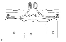
Standard:
42 to 44 mm (1.6535 to 1.7323 in.)
(e) Adjust the position of the fuel tank assembly to achieve the required difference in clearance between the left and right sides of the fuel tank assembly and the body.
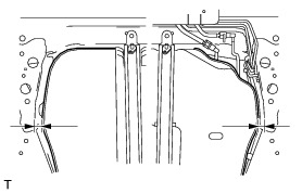
Standard:
Below 2 mm (0.0787 in.)
(f) Tighten the 4 bolts in the order shown in the illustration.
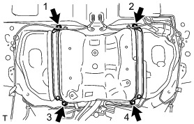
Torque : 33 Nm (337 kgf-cm, 24 ft-lbf)
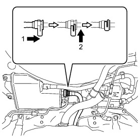
5. INSTALL CHARCOAL CANISTER ASSEMBLY
(a) Connect the quick connector as indicated by the arrows in the order shown in the illustration.
6. CONNECT FUEL TANK VENT HOSE SUB-ASSEMBLY
(a) Engage the clamp to install the tube.
(b) Connect the fuel tank vent hose sub-assembly with the clamp.
7. CONNECT FUEL TANK TO FILLER PIPE HOSE
(a) Connect the fuel tank to filler pipe hose to the fuel tank filler pipe sub-assembly with the clamp.
(b) Tighten the hose clamp bolt.
Torque : 2.5 Nm (25 kgf-cm, 22 in-lbf)
8. REMOVE NO. 3 PARKING BRAKE CABLE ASSEMBLY Installation
9. REMOVE NO. 2 PARKING BRAKE CABLE ASSEMBLY Installation
10. INSTALL NO. 3 FUEL TANK PROTECTOR
(a) Install the No. 3 fuel tank protector with a new nut and 2 clips.
Torque : 9.0 Nm (92 kgf-cm, 80 in-lbf)
11. INSTALL REAR SUSPENSION MEMBER SUB-ASSEMBLY
Installation
12. INSTALL FUEL TANK RETURN TUBE Installation
13. INSTALL FUEL SUCTION TUBE ASSEMBLY WITH PUMP AND GAUGE Installation
14. ADD FUEL
15. CONNECT CABLE TO NEGATIVE BATTERY TERMINAL Installation
16. INSPECT FOR FUEL LEAK Fuel System
17. INSTALL NO. 2 REAR FLOOR SERVICE HOLE COVER Installation
18. INSTALL REAR FLOOR SERVICE HOLE COVER Installation
19. INSTALL SEPARATE TYPE REAR SEAT CUSHION ASSEMBLY LH Installation
20. INSTALL SEPARATE TYPE REAR SEAT CUSHION ASSEMBLY RH Installation