Part 1
INTRODUCTION: REPAIR INSTRUCTION: PRECAUTION; 2013 MY FR-S [03/2012 -]
1. BASIC REPAIR HINT
(a) HINTS ON OPERATIONS


CAUTION:
*: Be sure to perform these checks properly, Not performing these checks properly after finishing work can lead to serious accident or injury.
(b) JACKING UP AND SUPPORTING THE VEHICLE
(1) Care must be taken when jacking up and supporting the vehicle. Be sure to lift and support the vehicle at the proper locations.
(c) PRECOATED PARTS


(1) Precoated parts are bolts and nuts that are coated with seal lock adhesive at the factory.
(2) If a precoated part is retightened, loosened or moved in any way, it must be recoated with the specified adhesive.
(3) When reusing a precoated part, clean off the old adhesive and dry the part with compressed air. Then apply new seal lock adhesive appropriately to that part.
(4) Some seal lock agents harden slowly. You may have to wait for the seal lock adhesive to harden.
(d) GASKETS
(1) When necessary, use a sealer on gaskets to prevent leaks.
(e) BOLTS, NUTS AND SCREWS
(1) Carefully follow all the specifications for tightening torque. Always use a torque wrench.
(2) Make sure that no foreign matter (burrs, paint, etc.) gets trapped under the heads of the bolts and nuts when tightening them.
(f) FUSES


(1) When inspecting a fuse, check that the wire of the fuse is not broken.
(2) If the wire of a fuse is broken, confirm that there are no shorts in its circuit.
(3) When a fuse is replaced, a fuse with the same amperage rating must be used.

(g) CLIPS
(1) The removal and installation methods of typical clips used for vehicle body parts are shown in the table below.
HINT
If clips are damaged during a procedure, always replace the damaged clips with new ones.


(h) CLAWS
(1) The removal and installation methods of typical claws used for vehicle body parts are shown in the table below.
HINT
If claws are damaged during a procedure, always replace the cap or cover that has damaged claws with a new one.

(i) HINGES, GUIDES, CLAMPS, PINS, ETC.
(1) The removal and installation methods of typical hinges, guides, clamps and pins used for vehicle body parts are shown in the table below.
HINT
If clamps are damaged during a procedure, always replace the cap or cover that has damaged clamps with a new one.

(j) REMOVAL AND INSTALLATION OF VACUUM HOSES
(1) To disconnect a vacuum hose, pull and twist it from the end of the hose. Do not pull it from the middle of the hose as this may damage the hose.


(2) When disconnecting vacuum hoses, use tags to identify where they should be reconnected.

(3) After completing any hose related repairs, double-check that the vacuum hoses are properly connected. The label under the hood shows the proper layout.
(4) When using a vacuum gauge, never force the hose onto a connector that is too large. If a hose has been stretched, air may leak. Use a step-down adapter if necessary.
(k) TORQUE WHEN USING TORQUE WRENCH WITH EXTENSION TOOL

(1) Use the formula below to calculate special torque values for situations where SST or an extension tool is combined with a torque wrench.

* Formula
T' = (L2/(L1 + L2))*T

NOTICE:
If an extension tool or SST is combined with a torque wrench and used to tighten to a torque specification in this service information, the actual torque will be excessive and parts will be damaged.
2. FOR VEHICLES EQUIPPED WITH SRS AIRBAG AND SEAT BELT PRETENSIONER
This vehicle is equipped with a Supplemental Restraint System (SRS).
CAUTION:
* Before performing pre-disposal deployment of any SRS component, review and closely follow all applicable environmental and hazardous material regulations. Pre-disposal deployment may be considered hazardous material treatment.
* Failure to carry out the service operations in the correct sequence could cause the SRS to unexpectedly deploy during servicing and lead to serious injury. Furthermore, if a mistake is made when servicing the SRS, it is possible that the SRS may fail to operate properly. Before servicing (including removal or installation of parts, inspection or replacement), be sure to read the following section carefully.
(a) GENERAL NOTICE
(1) The power window system utilizes a mechanism in which the door glass moves down slightly when the door is opened, and in which the glass moves up when the door closed in order to prevent the door molding from being damaged. When the negative (-) battery terminal needs to be disconnected for servicing, fully open the driver and passenger door glasses in advance.
(2) As malfunctions of the SRS are difficult to confirm, the Diagnostic Trouble Codes (DTCs) become the most important source of information when troubleshooting. When troubleshooting the SRS, always check for DTCs before disconnecting the battery.
(3) In the event of a collision, carry out an inspection using diagnosis even if the SRS airbag and pretensioner parts do not operate.
(4) Work must be started at least 90 seconds after the ignition switch is turned off and after the cable is disconnected from the negative (-) battery terminal.
The SRS is equipped with a back-up power source. If work is started within 90 seconds after turning the ignition switch off and disconnecting the cable from the negative (-) battery terminal, the SRS may deploy.
When the cable is disconnected from the negative (-) battery terminal, the clock and audio system memory will be cleared. Before starting work, make a note of the settings of each memory system. When work is finished, reset the clock and audio system as before.
CAUTION:
Never use a back-up power source (battery or other) to avoid clearing the system memory. The back-up power source may inadvertently power the SRS and cause it to deploy.
(5) If the vehicle has been involved in a minor collision where the SRS does not deploy, the horn button assembly, instrument panel passenger airbag assembly, knee airbag assembly, front seat airbag assembly, curtain shield airbag assembly and front seat outer belt assembly should be inspected before further use of the vehicle.
(6) Never use SRS parts from another vehicle. When replacing parts, use new ones.
(7) Before repairs, remove the airbag sensor assemblies if impacts are likely to be applied to the sensor during repairs.
(8) Never disassemble and attempt to repair any airbag sensor assemblies or airbag assemblies.
1 Horn button assembly
2 Instrument panel passenger airbag assembly
3 Front seat airbag assembly
4 Curtain shield airbag assembly
5 Front seat outer belt assembly
(9) Replace the airbag sensor assemblies and the airbag assemblies if: 1) damage has occurred from being dropped, or 2) cracks, dents or other defects in the case, bracket or connector are present.
(10) Do not directly expose the airbag sensor assemblies or airbag assemblies to hot air or flames.
(11) Use a voltmeter/ohmmeter with high impedance (minimum = 10 kOhms) for troubleshooting electrical circuits.
(12) Information labels are attached to the SRS components. Follow the instructions on the labels.
(13) After work on the SRS is completed, check the SRS warning light.
(b) SPIRAL CABLE SUB-ASSEMBLY
(1) The steering wheel must be fitted correctly to the steering column with the spiral cable sub-assembly at the neutral position. Otherwise, cable damage and other problems may occur. Refer to the information about correct installation of the steering wheel Installation.
(c) HORN BUTTON ASSEMBLY
(1) Always place a removed or new horn button assembly with the surface facing upward. Placing the horn button assembly with the pad surface facing downward could cause a serious accident if the airbag deploys. Also, do not place anything on top of the horn button assembly.
(2) Never measure the resistance of the airbag squib. This may cause the airbag to deploy, which could cause serious injury.
(3) Grease or detergents of any kind should not be applied to the horn button assembly.
(4) Store the horn button assembly in an area where the ambient temperature is below 93°C (199°F), the humidity is not high and there is no electrical noise.
(5) Before using an electric welder anywhere on the vehicle, disconnect the airbag ECU assembly connectors. These connectors contain shorting springs. This feature reduces the possibility of the airbag deploying due to current entering the squib wiring.
(6) When disposing of the vehicle or the horn button assembly by itself, the airbag should be deployed using SST before disposal Steering Pad. Deploy the airbag in a safe place away from electrical noise.
(d) INSTRUMENT PANEL PASSENGER AIRBAG ASSEMBLY
(1) Always place a removed or new instrument panel passenger airbag assembly with the pad surface facing upward. Placing the airbag assembly with the airbag deployment direction facing downward could cause a serious accident if the airbag deploys.
(2) Never measure the resistance of the airbag squib. This may cause the airbag to deploy, which could cause serious injury.
(3) Grease or detergents of any kind should not be applied to the instrument panel passenger airbag assembly.
(4) Store the airbag assembly in an area where the ambient temperature is below 93°C (199°F), the humidity is not high and there is no electrical noise.
(5) Before using an electric welder anywhere on the vehicle, disconnect the airbag ECU assembly connectors. These connectors contain shorting springs. This feature reduces the possibility of the airbag deploying due to current entering the squib wiring.
(6) When disposing of the vehicle or the instrument panel passenger airbag assembly unit by itself, the airbag should be deployed using SST before disposal Front Passenger Airbag Assembly. Deploy the airbag in a safe place away from electrical noise.
(e) FRONT SEAT AIRBAG ASSEMBLY
(1) Always place a removed or new front seat airbag assembly with the airbag deployment direction facing upward.
(2) Never measure the resistance of the airbag squib. This may cause the airbag to deploy, which could cause serious injury.
(3) Grease or detergents of any kind should not be applied to the front seat airbag assembly.
(4) Store the airbag assembly in an area where the ambient temperature is below 93°C (199°F), the humidity is not high and there is no electrical noise.
(5) Before using an electric welder anywhere on the vehicle, disconnect the airbag ECU assembly connectors. These connectors contain shorting springs. This feature reduces the possibility of the airbag deploying due to current entering the squib wiring.
(6) When disposing of a vehicle or the front seat airbag assembly unit by itself, the airbag should be deployed using SST before disposal Front Seat Side Airbag Assembly. Deploy the airbag in a safe place away from electrical noise.
(f) CURTAIN SHIELD AIRBAG ASSEMBLY
(1) Always place a removed or new curtain shield airbag assembly in a clear plastic bag, and keep it in a safe place.
CAUTION:
The plastic bag should be disposed of after use.
NOTICE:
Never disassemble the curtain shield airbag assembly.
(2) Never measure the resistance of the airbag squib. This may cause the airbag to deploy, which could cause serious injury.
(3) Grease or detergents of any kind should not be applied to the curtain shield airbag assembly.
(4) Store the airbag assembly in an area where the ambient temperature is below 93°C (199°F), the humidity is not high and there is no electrical noise.
(5) Before using an electric welder anywhere on the vehicle, disconnect the airbag ECU assembly connectors. These connectors contain shorting springs. This feature reduces the possibility of the airbag deploying due to current entering the squib wiring.
(6) When disposing of a vehicle or the curtain shield airbag assembly unit by itself, the airbag should be deployed using SST before disposal Curtain Shield Airbag Assembly. Deploy the airbag in a safe place away from electrical noise.
(g) FRONT SEAT OUTER BELT ASSEMBLY (SEAT BELT PRETENSIONER)
(1) Never measure the resistance of the front seat outer belt assembly. This may cause the pretensioner of the front seat outer belt assembly to activate, which could cause serious injury.
(2) Never disassemble the front seat outer belt assembly.
(3) Never install the front seat outer belt assembly on another vehicle.
(4) Store the seat outer belt assembly in an area where the ambient temperature is below 80°C (176°F), the humidity is not high and there is no electrical noise.
(5) Before using an electric welder anywhere on the vehicle, disconnect the airbag ECU assembly connectors. These connectors contain shorting springs. This feature reduces the possibility of the airbag deploying due to current entering the squib wiring.
(6) When disposing of a vehicle or the front seat outer belt assembly unit by itself, the front seat outer belt assembly should be activated before disposal Procedures. Activate the front seat outer belt assembly in a safe place away from electrical noise.
(7) As the front seat outer belt assembly is hot after being activated, allow some time for it to cool down sufficiently before disposal. Never apply water to cool down the front seat outer belt assembly.
(8) Grease, detergents, oil or water should not be applied to the front seat outer belt assembly.
(h) AIRBAG ECU ASSEMBLY
(1) Never reuse a airbag ECU assembly that has been involved in a collision where the SRS has deployed.
(2) The connectors to the airbag ECU assembly should be connected or disconnected with the airbag ECU assembly installed to the vehicle. If the connectors are connected or disconnected while the airbag ECU assembly is not installed, the SRS may activate.
(3) Work must be started at least 90 seconds after the ignition switch is turned off and the cable is disconnected from the negative (-) battery terminal, even if only loosening the bolts of the airbag ECU assembly.
(i) WIRE HARNESS AND CONNECTOR
(1) All the connectors in the system are a standard yellow color. If an SRS wire harness has an open circuit or a connector is broken, replace it.
3. VEHICLES WITH OCCUPANT CLASSIFICATION SYSTEM
(a) After removing or replacing the seat cushion cover, ensure that the worker gets into and out of the front passenger seat after installing the seat, and confirm that the front passenger airbag ON/OFF indicator switches between on and off. Confirm that the ON indicator is lit when the front passenger seat is occupied, and that the OFF indicator is lit when the front passenger seat is vacant.
(b) The occupant detection ECU, occupant detection sensor, seat cushion pad, and seat cushion frame comprise the seat cushion pad and frame assembly. Therefore, never remove the occupant detection ECU and occupant detection sensor from the seat cushion pad and frame assembly.
(c) If the seat cushion cover is removed, make sure to replace the hang wires on the seat cushion cover side with new ones.
(d) Do not replace or alter the cover or filling of the front passenger seat.
(e) Do not install accessories other than genuine accessories (for example, audio amps, etc.) under the front passenger seat.
(f) Do not place magnetized items near the seat belt buckle switch.
(g) When packages or electronic items are placed on the front passenger seat, the occupant classification system may not properly detect the weight of a passenger, and the front passenger airbag may deploy in the event of a collision. When driving after work on the front passenger seat, do not place packages or electronic items on the front passenger seat.
4. ELECTRONIC CONTROL

NOTICE:
* The power window system utilizes a mechanism in which the door glass moves down slightly when the door is opened, and in which the glass moves up when the door closed in order to prevent the door molding from being damaged. When the negative (-) battery terminal needs to be disconnected for servicing, fully open the driver and passenger door glasses in advance.
* Certain systems need to be initialized after disconnecting and reconnecting the cable from the negative (-) battery terminal.
* After the ignition switch is turned off, the navigation receiver assembly (for Navigation Receiver Type) or radio and display receiver assembly (for Radio and Display Type with Intuitive Parking Assist System) records various types of memory and settings. As a result, after turning the ignition switch off, make sure to wait at least 60 seconds before disconnecting the cable from the negative (-) battery terminal.
(a) DISCONNECTING AND RECONNECTING NEGATIVE BATTERY CABLE
(1) Before performing work on electronic components, disconnect the cable from the negative (-) battery terminal to prevent damage to the electrical system or components.
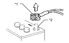
(2) When disconnecting the cable, turn the ignition switch and headlight switch off and loosen the cable nut completely. Perform these operations without twisting or prying the cable. Then disconnect the cable.
(3) Clock settings, radio settings, audio system memory, DTCs and other data will be cleared when the cable is disconnected from the negative (-) battery terminal. Write down any necessary data before disconnecting the cable.
(b) HANDLING OF ELECTRONIC PARTS


(1) Do not open the cover or case of the ECU unless absolutely necessary. If the IC terminals are touched, the IC may be rendered inoperative by static electricity.
(2) Do not pull on the wires when disconnecting electronic connectors. Pull on the connector itself.
(3) Do not drop electronic components, such as sensors or relays. If they are dropped on a hard surface, they should be replaced.
(4) When cleaning the engine components with steam, protect the electronic components, air filter and emission-related components from water.
(5) Never use an impact wrench to remove or install temperature switches or temperature sensors.
(6) When measuring the resistance between terminals of a wire connector, insert the tester probe carefully to prevent the terminals from bending.
5. REMOVAL AND INSTALLATION OF FUEL CONTROL PARTS
(a) PLACE FOR REMOVING AND INSTALLING FUEL SYSTEM PARTS
(1) Work in a location with good air ventilation that does not have welders, grinders, drills, electric motors, stoves, or any other ignition sources nearby.
(2) Never work in a pit or near a pit as fuel vapors will collect there.
(b) REMOVING AND INSTALLING FUEL SYSTEM PARTS
(1) Prepare a fire extinguisher before starting work.
(2) To prevent static electricity, install a ground wire between the fuel changer and vehicle, and do not spray the surrounding area with water. Be careful when performing work in this area, as the floor surface will become slippery. Do not clean up gasoline spills with water, as this may cause the gasoline to spread, and possibly create a fire hazard.
(3) Avoid using electric motors, work lights and other electric equipment that can cause sparks or high temperatures.
(4) Avoid using iron hammers as they may create sparks.
(5) Dispose of fuel-contaminated cloth separately using a fire resistant container.