Starter (For Automatic Transmission)
FA20 STARTING: STARTER (for Automatic Transmission): INSPECTION; 2013 MY FR-S [03/2012 -]
1. INSPECT STARTER ASSEMBLY
CAUTION:
As a large electric current passes through the cable during this inspection, a thick cable must be used. If not, the cable may become hot and cause injury.
NOTICE:
The following tests must each be performed within 3 to 5 seconds to prevent the coil from burning out.
(a) Mount the starter in a vise between aluminum plates.
(b) Perform a pull-in test.
(1) Remove the nut, and then disconnect the lead wire from terminal C.
(2) Connect the battery to the starter as shown in the illustration. Check that the clutch pinion gear extends.
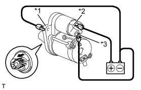

If the clutch pinion gear does not move, inspect the magnet starter switch assembly. If the magnet starter switch assembly is not as specified, replace it.
(c) Perform a holding test.
(1) Disconnect the negative (-) terminal lead from terminal C while the conditions specified in the pull-in test above are maintained. Check that the pinion gear remains out.
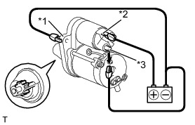
If the clutch pinion gear returns inward, inspect the magnet starter switch assembly. If the magnet starter switch assembly is not as specified, replace it.
(d) Inspect the clutch pinion gear return.
(1) Disconnect the negative (-) terminal lead from the starter body. Check that the clutch pinion gear returns inward.
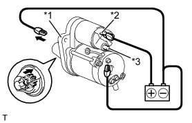

If the clutch pinion gear does not return inward, inspect the magnet starter switch assembly. If the magnet starter switch assembly is not as specified, replace it.
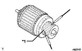
(e) Perform an operation test without load.
(1) Connect the lead wire to terminal C with the nut.
Torque : 10 Nm (102 kgf-cm, 7 ft-lbf)
(2) Connect the battery and an ammeter to the starter as shown in the illustration.
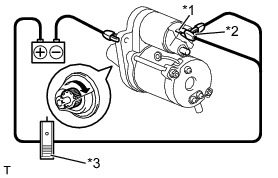
(3) Check that the starter rotates smoothly and steadily while the clutch pinion gear is extended. Then measure the current.
Standard Current:

If the result is not as specified, inspect the starter assembly.
HINT
Inspect the starter armature assembly, starter commutator end frame assembly and magnet starter switch assembly. If there is a malfunction, replace the part and perform again this test.
2. INSPECT STARTER ARMATURE ASSEMBLY
(a) Check the commutator for dirt and/or burns on the surface.
If the surface is dirty or burnt, correct it with sandpaper (No. 400) or a lathe. If necessary, replace the starter armature assembly.
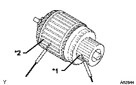
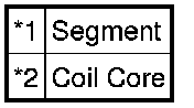
(b) Inspect the commutator for an open circuit.
(1) Measure the resistance according to the value(s) in the table below.
Standard Resistance:
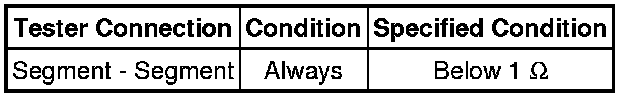
If the result is not as specified, replace the starter armature assembly.
(c) Inspect the commutator for short circuits.
(1) Measure the resistance according to the value(s) in the table below.
Standard Resistance:
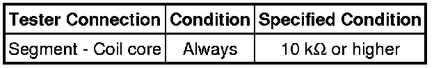
If the result is not as specified, replace the starter armature assembly.
(d) Check the commutator for signs of seizure or stepped wear caused by roughness of the surface. If there is light wear, use sandpaper to repair.
(e) Check for runout on the commutator. If excessive, replace the armature.
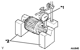
Standard runout:
0.02 mm (0.0008 in.)
Maximum runout:
0.05 mm (0.002 in.)
If the result is not as specified, replace the starter armature assembly.
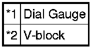
(f) Using vernier caliper, measure the commutator diameter.

Standard diameter:
29 mm (1.1417 in.)
Minimum diameter:
28 mm (1.1024 in.)
If the diameter is less than the minimum, replace the starter armature assembly.
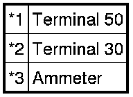
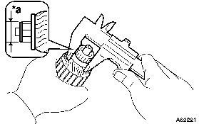
(g) Using vernier caliper, measure the under cut depth of the segment. If it is not within the standard, replace the starter armature assembly.
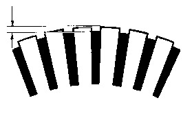
Standard depth:
0.7 mm (0.0276 in.)
Minimum depth:
0.2 mm (0.0079 in.)
3. INSPECT STARTER BRUSH HOLDER ASSEMBLY
(a) Using a vernier caliper, measure the brush length.
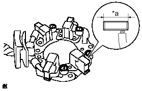

Standard length:
14.4 mm (0.5669 in.)
Minimum length:
9.0 mm (0.3543 in.)
If the length is less than the minimum, replace the starter brush holder assembly.
(b) Measure the resistance according to the value(s) in the table below.
Standard Resistance:
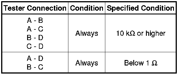
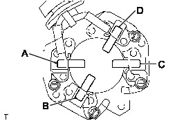
If the result is not as specified, replace the starter brush holder assembly.
4. INSPECT MAGNET STARTER SWITCH ASSEMBLY
(a) Check the plunger.
(1) Push in the plunger and check that it returns quickly to it is original position.
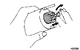
If necessary, replace the magnet starter switch assembly.
(b) Inspect the pull-in coil.
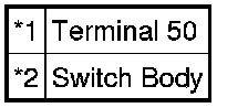
(1) Measure the resistance according to the value(s) in the table below.
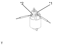
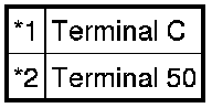
Standard Resistance:
If the result is not as specified, replace the magnet starter switch assembly.
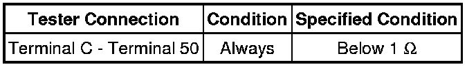
(c) Inspect the holding coil.
(1) Measure the resistance according to the value(s) in the table below.
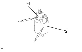
Standard Resistance:
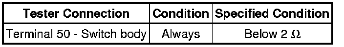
If the result is not as specified, replace the magnet starter switch assembly.