Reassembly
STEERING COLUMN: STEERING COLUMN ASSEMBLY: REASSEMBLY; 2013 MY FR-S [03/2012 -]
NOTICE:
* When using a vise, do not overtighten it.
* Do not drop the steering column assembly, strike it with tools or subject it to impacts.
* If the steering column assembly is subjected to an impact, replace it with a new one.
* Do not pull the wire harness of the steering column assembly.
* Do not allow any moisture to come into contact with the steering column sub-assembly.
* Do not loosen any bolts not mentioned in the procedure.
1. INSTALL IGNITION OR STARTER SWITCH ASSEMBLY
(a) Install the ignition or starter switch assembly with the 2 screws to the steering column upper bracket assembly.

2. INSTALL IGNITION SWITCH LOCK CYLINDER ASSEMBLY
(a) Make sure that the ignition switch lock cylinder assembly is in the ACC position.

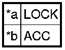
(b) Install the ignition switch lock cylinder assembly to the steering column upper bracket assembly.
(c) Make sure that the ignition switch lock cylinder assembly is securely installed.
3. INSTALL KEY INTERLOCK SOLENOID (for Automatic Transmission)
(a) Engage the clamp.

(b) Install the 2 screws and the key interlock solenoid to the steering column upper bracket assembly.
4. INSTALL UN-LOCK WARNING SWITCH ASSEMBLY
(a) Slide the unlock warning switch assembly and engage the 2 claws to install the unlock warning switch assembly to the steering column upper bracket assembly as shown in the illustration.

5. INSTALL TRANSPONDER KEY AMPLIFIER
(a) Align the transponder key amplifier with the steering column upper bracket assembly. Tilt the transponder key amplifier slightly and slide it into position.
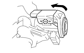
(b) Push the transponder key amplifier, and engage the 2 claws to install the transponder key amplifier to the steering column upper bracket assembly.
6. INSPECT STEERING LOCK OPERATION Testing and Inspection
7. INSTALL STEERING COLUMN UPPER WITH SWITCH BRACKET ASSEMBLY
(a) Secure the steering column assembly in a vise.
(b) Temporarily install the steering column upper with switch bracket assembly to the steering column assembly with new tapered-head bolt.

(c) Tighten the tapered-head bolt until the bolt head break off.