Part 2
TX6A AUTOMATIC TRANSMISSION / TRANSAXLE: AUTOMATIC TRANSMISSION UNIT: DISASSEMBLY; 2013 MY FR-S [03/2012 -] (Continued)
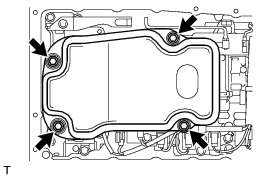
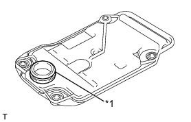
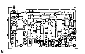
16. REMOVE VALVE BODY OIL STRAINER ASSEMBLY
(a) Turn over the automatic transmission case sub-assembly.
(b) Remove the 4 bolts and the valve body oil strainer assembly from the transmission valve body assembly.
(c) Remove the O-ring from the valve body oil strainer assembly.

17. REMOVE TRANSMISSION WIRE
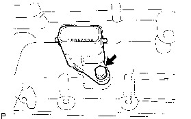
(a) Remove the bolt and the temperature sensor clamp, and separate the ATF temperature sensor.
(b) Remove the bolt and the valve body wire harness clamp.
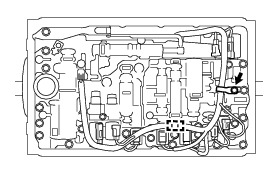
(c) Disengage the wire harness clamp.
(d) Disconnect the 9 solenoid valve connectors.
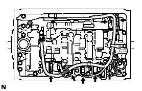
(e) Remove the bolt and pull out the transmission wire.
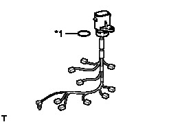
(f) Remove the O-ring from the transmission wire.

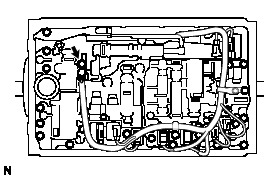
18. REMOVE TRANSMISSION VALVE BODY ASSEMBLY
(a) Remove the bolt, detent spring cover and the detent spring from the transmission valve body assembly.
(b) Remove the 19 bolts and the transmission valve body assembly from the automatic transmission case sub-assembly.
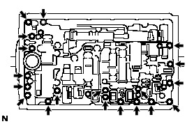
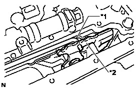
(c) Disconnect the manual valve connecting rod sub-assembly from the manual valve lever sub-assembly.
19. REMOVE TRANSMISSION CASE GASKET
(a) Remove the 3 transmission case gaskets from the automatic transmission case sub-assembly.
20. REMOVE BRAKE DRUM GASKET
(a) Remove the 3 brake drum gaskets from the automatic transmission case sub-assembly.
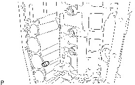
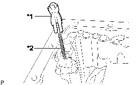
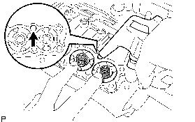
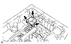
21. REMOVE CHECK BALL BODY
(a) Remove the check ball body and the compression spring from the automatic transmission case sub-assembly.
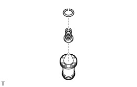
22. REMOVE C-2 ACCUMULATOR PISTON
(a) While blowing compressed air into the oil hole, remove the C-2 accumulator piston and the spring from the automatic transmission case sub-assembly.
NOTICE:
Take care as the C-3 and B-3 accumulator pistons may jump out.
(b) Remove the 2 O-rings from the C-2 accumulator piston.
(c) Using a screwdriver, remove the snap ring and the spring sub-assembly from the C-2 accumulator piston.
NOTICE:
Be careful not to damage the C-2 accumulator piston.
HINT
Tape the screwdriver tip before use.
23. REMOVE B-3 ACCUMULATOR PISTON
(a) While blowing compressed air into the oil hole, remove the B-3 accumulator piston and the spring from the automatic transmission case sub-assembly.
NOTICE:
Take care as the C-3 accumulator piston may jump out.
(b) Remove the 2 O-rings from the B-3 accumulator piston.
(c) Using a screwdriver, remove the snap ring and the spring sub-assembly from the B-3 accumulator piston.
NOTICE:
Be careful not to damage the B-3 accumulator piston.
HINT
Tape the screwdriver tip before use.
24. REMOVE C-3 ACCUMULATOR PISTON
(a) While blowing compressed air into the oil hole, remove the C-3 accumulator piston and the 2 springs from the automatic transmission case sub-assembly.
(b) Remove the 2 O-rings from the C-3 accumulator piston.
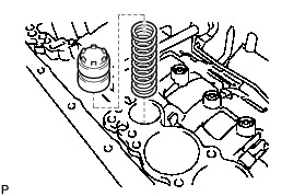
25. REMOVE B-1 ACCUMULATOR VALVE
(a) Remove the B-1 accumulator valve and the spring from the automatic transmission case sub-assembly.
26. REMOVE PARKING LOCK PAWL BRACKET
(a) Remove the 3 bolts and the parking lock pawl bracket from the automatic transmission case sub-assembly.
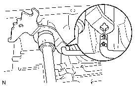
27. REMOVE PARKING LOCK ROD SUB-ASSEMBLY
(a) Remove the parking lock rod sub-assembly from the manual valve lever sub-assembly.
28. REMOVE PARKING LOCK PAWL SHAFT
(a) Pull out the parking lock pawl shaft from the front side, and remove the parking lock pawl and the torsion spring.
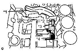
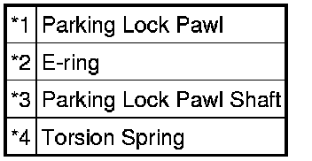
(b) Remove the E-ring from the parking lock pawl shaft.
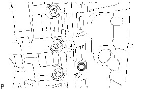
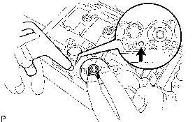
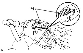
29. REMOVE MANUAL VALVE LEVER SUB-ASSEMBLY
(a) Using a screwdriver and a hammer, cut off the spacer and remove it from the manual valve lever shaft.

NOTICE:
Be careful not to damage the manual valve lever shaft.
HINT
Tape the screwdriver tip before use.
(b) Using a pin punch 3 mm and a hammer, drive out the spring pin.
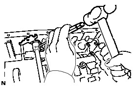
HINT
Slowly drive out the spring pin so that it does not fall into the automatic transmission case sub-assembly.
(c) Pull the manual valve lever shaft out through the case and remove the manual valve lever sub-assembly.
30. REMOVE MANUAL VALVE LEVER SHAFT OIL SEAL
(a) Using a screwdriver, pry out the 2 manual valve lever shaft oil seals from the automatic transmission case sub-assembly.
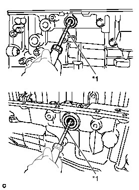

NOTICE:
Be careful not to damage the automatic transmission case sub-assembly.
HINT
Tape the screwdriver tip before use.