Part 3
TX6A AUTOMATIC TRANSMISSION / TRANSAXLE: AUTOMATIC TRANSMISSION UNIT: DISASSEMBLY; 2013 MY FR-S [03/2012 -] (Continued)
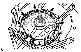
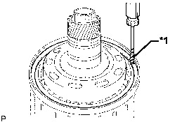
31. REMOVE OIL PUMP ASSEMBLY
(a) Remove the 9 bolts.
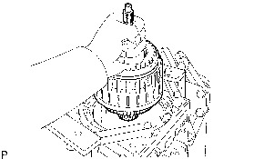
(b) Using a screwdriver, pull out the oil pump assembly from the automatic transmission case sub-assembly.
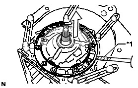

NOTICE:
Be careful not to damage the oil pump assembly or automatic transmission case sub-assembly.
HINT
Tape the screwdriver tip before use.
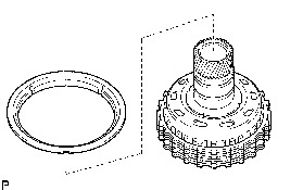
(c) Remove the No. 1 thrust bearing race from the oil pump assembly.
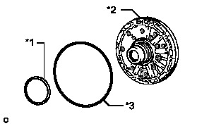
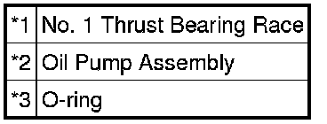
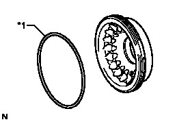
(d) Remove the O-ring from the oil pump assembly.
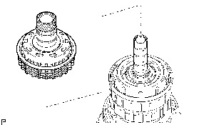
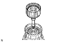
32. REMOVE CLUTCH DRUM AND INPUT SHAFT ASSEMBLY
(a) Remove the clutch drum and input shaft assembly from the automatic transmission case sub-assembly.
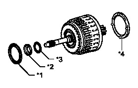
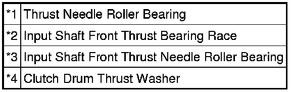
(b) Remove the clutch drum thrust washer, thrust needle roller bearing, input shaft front thrust bearing race and the input shaft front thrust needle roller bearing from the clutch drum and input shaft assembly.
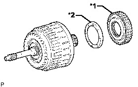
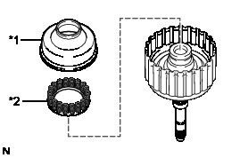
33. REMOVE NO. 2 ONE-WAY CLUTCH ASSEMBLY
(a) Remove the No. 2 one-way clutch assembly and the input shaft clutch drum thrust washer from the clutch drum and input shaft assembly.
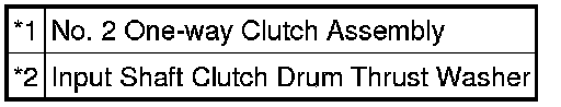
34. SUPPORT CLUTCH DRUM AND INPUT SHAFT ASSEMBLY
(a) Place the oil pump assembly onto the torque converter assembly, and then place the clutch drum and input shaft assembly onto the oil pump assembly.
35. REMOVE REVERSE CLUTCH HUB SUB-ASSEMBLY
(a) Using a screwdriver, remove the snap ring from the reverse clutch piston sub-assembly.

NOTICE:
Be careful not to damage the reverse clutch piston sub-assembly.
HINT
Tape the screwdriver tip before use.
(b) Remove the reverse clutch hub sub-assembly from the reverse clutch drum sub-assembly.
36. REMOVE REVERSE CLUTCH REACTION SLEEVE
(a) Remove the reverse clutch reaction sleeve from the reverse clutch hub sub-assembly.
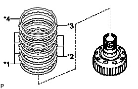
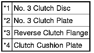
37. REMOVE NO. 3 CLUTCH DISC (REAR CLUTCH DISC)
(a) Remove the clutch cushion plate, reverse clutch flange, 4 No. 3 clutch discs and the 3 No. 3 clutch plates from the reverse clutch hub sub-assembly.
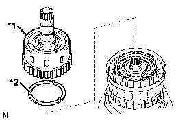
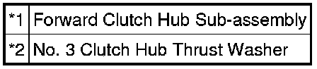
38. REMOVE FORWARD CLUTCH HUB SUB-ASSEMBLY
(a) Remove the forward clutch hub sub-assembly and the No. 3 clutch hub thrust washer from the reverse clutch drum sub-assembly.
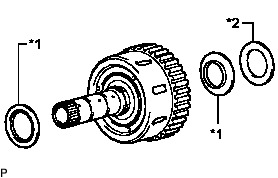
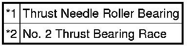
(b) Remove the 2 thrust needle roller bearings and the No. 2 thrust bearing race from the forward clutch hub sub-assembly.
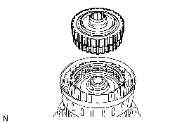
39. REMOVE COAST CLUTCH HUB SUB-ASSEMBLY
(a) Remove the coast clutch hub sub-assembly from the reverse clutch drum sub-assembly.
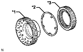
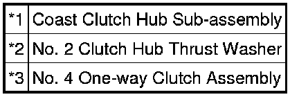
40. REMOVE NO. 4 ONE-WAY CLUTCH ASSEMBLY
(a) Remove the No. 4 one-way clutch assembly and the No. 2 clutch hub thrust washer from the coast clutch hub sub-assembly.
41. REMOVE NO. 1 CLUTCH DISC (FORWARD CLUTCH DISC)
(a) Using a screwdriver, remove the snap ring.
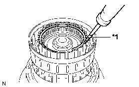

NOTICE:
Be careful not to damage the input shaft.
HINT
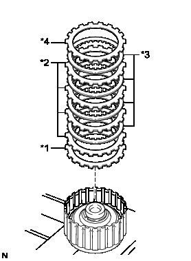
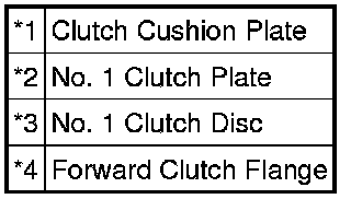
Tape the screwdriver tip before use.
(b) Remove the forward clutch flange, 4 No. 1 clutch discs, 4 No. 1 clutch plates and the clutch cushion plate from the input shaft.
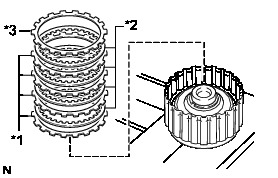
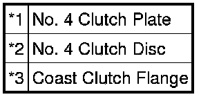
42. REMOVE NO. 4 CLUTCH DISC (COAST CLUTCH DISC)
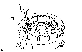
(a) Using a screwdriver, remove the snap ring.

NOTICE:
Be careful not to damage the forward clutch piston sub-assembly.
HINT
Tape the screwdriver tip before use.
(b) Remove the coast clutch flange, 4 No. 4 clutch discs and the 4 No. 4 clutch plates from the forward clutch piston sub-assembly.
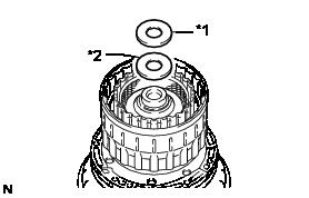
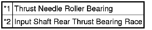
43. REMOVE INPUT SHAFT
(a) Remove the thrust needle roller bearing and the input shaft rear thrust bearing race from the input shaft.
(b) Remove the input shaft from the reverse clutch drum sub-assembly.
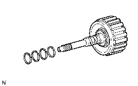
44. REMOVE CLUTCH DRUM OIL SEAL RING
(a) Remove the 4 clutch drum oil seal rings from the input shaft.
45. REMOVE NO. 1 CLUTCH BALANCER
(a) Place SST on the No. 1 clutch balancer, and compress the forward clutch return spring sub-assembly with a press.
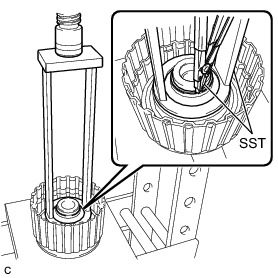
SST : 09387-00110
(b) Using SST, remove the snap ring.
SST : 09350-30020
09350-07070
(c) Remove the No. 1 clutch balancer and the forward clutch return spring sub-assembly from the input shaft.
(d) Remove the D-ring from the No. 1 clutch balancer.