Part 1
TX6A AUTOMATIC TRANSMISSION / TRANSAXLE: AUTOMATIC TRANSMISSION UNIT: REASSEMBLY; 2013 MY FR-S [03/2012 -]
1. BEARING POSITION


2. INSTALL NO. 4 BRAKE PISTON
(a) Coat 2 new O-ring with ATF, and install them to the brake reaction sleeve.


(b) Coat 2 new O-rings with ATF, and install them to the No. 4 brake piston.
(c) Install the No. 4 brake piston to the brake reaction sleeve.
NOTICE:
Be careful not to damage the O-rings.
3. INSTALL BRAKE REACTION SLEEVE
(a) With the No. 4 brake piston underneath (the rear side), install the brake reaction sleeve and the No. 4 brake piston to the automatic transmission case sub-assembly.


NOTICE:
Be careful not to damage the O-rings.
4. INSTALL 1ST AND REVERSE BRAKE PISTON
(a) Coat a new O-rings with ATF, and install it to the 1st and reverse brake piston.


(b) With the spring seat of the 1st and reverse brake piston facing upwards (the front side), place the 1st and reverse brake piston in the automatic transmission case sub-assembly.
NOTICE:
Be careful not to damage the O-ring.
5. INSTALL 1ST AND REVERSE BRAKE RETURN SPRING SUB-ASSEMBLY
(a) Place the 1st and reverse brake return spring sub-assembly onto the 1st and reverse brake piston.
(b) Place SST on the 1st and reverse brake return spring sub-assembly, and compress the 1st and reverse brake return spring sub-assembly.


SST : 09350-30020
09350-07050
(c) Using SST, install the snap ring.
SST : 09350-30020
09350-07070
6. INSTALL BRAKE APPLY TUBE
(a) Install the brake apply tube with its protruding part fitting into the groove of the automatic transmission case sub-assembly as shown in the illustration.

NOTICE:
Engage the 1st and reverse brake piston claw with the protrusion of the brake apply tube.
7. INSTALL REAR PLANETARY GEAR ASSEMBLY
(a) Install the thrust needle roller bearing to the automatic transmission case sub-assembly.

Bearing Diameter

(b) Install the thrust needle roller bearing to the rear planetary gear assembly.

Bearing and Race Diameter

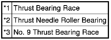
(c) Coat the No. 9 thrust bearing race and the thrust bearing race with petroleum jelly, and install them onto the rear planetary gear assembly.
(d) Install the rear planetary gear assembly to the automatic transmission case sub-assembly.

8. INSPECT PACK CLEARANCE OF NO. 4 BRAKE Transaxle Unit
9. INSTALL NO. 4 BRAKE DISC
(a) Install the 2 No. 4 brake flanges, 5 No. 4 brake discs and the 4 No. 4 brake plates to the automatic transmission case sub-assembly.


Installation order:
*1 - *2 - *3 - *2 - *3 - *2 - *3 - *2 - *3 - *2 - *1
NOTICE:
Make sure that the discs, plates and the flanges are installed in the correct order.
10. INSTALL BRAKE PLATE STOPPER SPRING
(a) Install the brake plate stopper spring to the automatic transmission case sub-assembly.

11. INSTALL REAR PLANETARY RING GEAR FLANGE SUB-ASSEMBLY
(a) Install the No. 8 thrust bearing race, thrust needle roller bearing, No. 7 thrust bearing race and the rear planetary ring gear flange sub-assembly to the intermediate shaft.


Bearing and Race Diameter

12. INSTALL NO. 3 ONE-WAY CLUTCH ASSEMBLY
(a) Install the No. 3 one-way clutch assembly and the one-way clutch inner race to the intermediate shaft.


13. INSTALL INTERMEDIATE SHAFT
(a) Install the intermediate shaft together with the No. 3 one-way clutch assembly to the automatic transmission case sub-assembly.

(b) Using SST, install the snap ring to the automatic transmission case sub-assembly.

SST : 09350-30020
09350-07060
14. INSTALL CENTER PLANETARY GEAR ASSEMBLY
(a) Install the center planetary gear assembly and the planetary sun gear to the automatic transmission case sub-assembly.


Bearing and Race Diameter

(b) Coat the No. 4 thrust bearing race with petroleum jelly, and install it onto the center planetary gear assembly.
(c) Install the thrust needle roller bearing to the center planetary gear assembly.
15. INSTALL NO. 2 BRAKE PISTON
(a) Coat 2 new O-rings with ATF, and install them to the No. 2 brake piston.


(b) Press the No. 2 brake piston into the No. 2 brake cylinder.
NOTICE:
Be careful not to damage the O-rings.
(c) Install the No. 2 brake piston to the automatic transmission case sub-assembly.
HINT
Install the No. 2 brake cylinder so that the projection protrudes from the upside of the automatic transmission case sub-assembly.
(d) Check that the oil pressure apply hole of the No. 2 brake cylinder aligns with the oil pressure apply hole of the automatic transmission case sub-assembly.

16. INSTALL NO. 2 BRAKE DISC
(a) Install the No. 2 brake piston return spring sub-assembly to the automatic transmission case sub-assembly as shown in the illustration.


NOTICE:
Make sure that the identification shape of the No. 2 brake piston return spring sub-assembly faces the upper right side as shown in the illustration.
(b) Install the 2 No. 2 brake flanges, 4 No. 2 brake discs and the 3 No. 2 brake plates to the automatic transmission case sub-assembly.


Installation order:
*1 - *2 - *3 - *2 - *3 - *2 - *3 - *2 - *1
NOTICE:
Make sure that the discs, plates and the flanges are installed in the correct order.
(c) Using SST and a screwdriver, compress the No. 2 brake piston return spring sub-assembly and install the snap ring to the automatic transmission case sub-assembly.


SST : 09350-30020
09350-07020
SST : 09380-60010
09381-06030
09381-06050
09381-06080
09381-06090
09381-06100
09381-06110
NOTICE:
Be careful not to damage the automatic transmission case sub-assembly.
HINT
Tape the screwdriver tip before use.
17. INSPECT PISTON STROKE OF NO. 2 BRAKE PISTON Transaxle Unit