Part 2
TX6A AUTOMATIC TRANSMISSION / TRANSAXLE: AUTOMATIC TRANSMISSION UNIT: REASSEMBLY; 2013 MY FR-S [03/2012 -] (Continued)
18. INSTALL NO. 1 BRAKE PISTON
(a) Coat 2 new O-rings with ATF, and install them to the No. 1 brake piston.


(b) Press the No. 1 brake piston into the No. 1 brake cylinder.
NOTICE:
Be careful not to damage the O-rings.
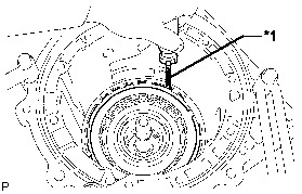
19. INSTALL BRAKE PISTON RETURN SPRING SUB-ASSEMBLY
(a) Install the brake piston return spring sub-assembly and the No. 1 brake cylinder to the automatic transmission case sub-assembly.


HINT
Install the No. 1 brake cylinder so that the projection protrudes from the upside of the automatic transmission case sub-assembly.
(b) Check that the oil pressure apply hole of the No. 1 brake cylinder aligns with the oil pressure apply hole of the automatic transmission case sub-assembly.

(c) Using SST and a screwdriver, compress the brake piston return spring sub-assembly and install the snap ring to the automatic transmission case sub-assembly.


SST : 09350-30020
09350-07020
SST : 09351-40010
09351-04010
09351-04020
NOTICE:
Be careful not to damage the automatic transmission case sub-assembly.
HINT
Tape the screwdriver tip before use.
20. INSTALL CENTER PLANETARY RING GEAR
(a) Install the front planetary ring gear flange sub-assembly to the center planetary ring gear.


(b) Using a screwdriver, install the snap ring.
NOTICE:
Be careful not to damage the center planetary ring gear.
HINT
Tape the screwdriver tip before use.
(c) Install the center planetary ring gear to the front planetary ring gear.
(d) Using a screwdriver, install the snap ring.


NOTICE:
* Be careful not to damage the front planetary ring gear.
* Install the snap ring to the front planetary ring gear so that both ends of the snap ring come to the center of a protrusion on the front planetary ring gear.
HINT
Tape the screwdriver tip before use.
21. INSTALL FRONT PLANETARY RING GEAR
(a) Install the front planetary ring gear to the automatic transmission case sub-assembly.

22. INSTALL FRONT PLANETARY GEAR ASSEMBLY
(a) Install the No. 2 planetary carrier thrust washer and the front planetary flange thrust needle roller bearing.


Bearing and Race Diameter

(b) Coat the front planetary flange rear thrust bearing race with petroleum jelly, and install it onto the front planetary ring gear.
(c) Install the front planetary gear assembly and the one-way clutch inner race sub-assembly to the automatic transmission case sub-assembly.


23. INSPECT PISTON STROKE OF NO. 1 BRAKE PISTON Transaxle Unit
24. INSTALL NO. 1 BRAKE DISC
(a) Install the No. 1 brake flange, 3 No. 1 brake discs and the 3 No. 1 brake plates to the automatic transmission case sub-assembly.


Installation order:
*1 - *2 - *1 - *2 - *1 - *2 - *3
NOTICE:
Make sure that the discs, plates and the flange are installed in the correct order.
25. INSTALL ONE-WAY CLUTCH ASSEMBLY
(a) Install the No. 1 planetary carrier thrust washer and the one-way clutch assembly to the automatic transmission case sub-assembly.


26. INSTALL 2ND BRAKE PISTON
(a) Coat 2 new O-rings with ATF, and install them to the 2nd brake piston.


(b) Press the 2nd brake piston into the 2nd brake cylinder.
NOTICE:
Be careful not to damage the O-rings.
(c) Using a screwdriver, install the No. 3 brake piston return spring sub-assembly to the 2nd brake cylinder with the snap ring.


NOTICE:
* Be sure that the end gap of the snap ring is not aligned with the spring retainer claw.
* Be careful not to damage the 2nd brake cylinder.
HINT
Tape the screwdriver tip before use.
27. INSTALL 2ND BRAKE CYLINDER
(a) Install the 2nd brake cylinder to the automatic transmission case sub-assembly.

(b) Check that the oil pressure apply hole of the 2nd brake cylinder aligns with the oil pressure apply hole of the automatic transmission case sub-assembly.

(c) Using SST, install the snap ring to the automatic transmission case sub-assembly.

SST : 09350-30020
09350-07060
28. INSTALL NO. 3 BRAKE DISC (2ND BRAKE DISC SET)
(a) Install the No. 3 brake flange, 3 No. 3 brake discs and the 3 No. 3 brake plates to the automatic transmission case sub-assembly.


Installation order:
*1 - *2 - *1 - *2 - *1 - *2 - *3
NOTICE:
Make sure that the discs, plates and the flange are installed in the correct order.
(b) Using a screwdriver, install the snap ring to the automatic transmission case sub-assembly.

NOTICE:
Be careful not to damage the automatic transmission case sub-assembly.
HINT
Tape the screwdriver tip before use.
29. INSTALL DIRECT CLUTCH PISTON SUB-ASSEMBLY
(a) Coat 2 new O-rings with ATF, and install them to the direct clutch piston sub-assembly.


(b) Coat a new O-ring with ATF, and install it to the No. 2 clutch balancer.


(c) Install the No. 2 clutch balancer and the direct clutch return spring sub-assembly to the direct clutch piston sub-assembly.


(d) Press the direct clutch piston sub-assembly into the reverse clutch drum sub-assembly by hands.
NOTICE:
Be careful not to damage the O-rings.
(e) Place SST on the No. 2 clutch balancer, and compress the direct clutch return spring sub-assembly with a press.

SST : 09320-89010
NOTICE:
Stop pressing when the spring sheet is lowered to the place 1 to 2 mm (0.0394 to 0.0787 in.) from the snap ring groove to prevent the spring sheet from being deformed.
(f) Using SST, install the snap ring.
SST : 09350-30020
09350-07070
NOTICE:
* Be sure that the end gap of the snap ring is not aligned with the spring retainer claw.
* Do not expand the snap ring excessively.
(g) Set the end gap of the snap ring in the No. 2 clutch balancer as shown in the illustration.


30. INSTALL REVERSE CLUTCH PISTON SUB-ASSEMBLY
(a) Coat a new O-ring with ATF, and install it to the reverse clutch drum sub-assembly.


(b) Coat a new O-ring with ATF, and install it to the reverse clutch piston sub-assembly.


(c) Press the reverse clutch drum sub-assembly into the reverse clutch piston sub-assembly with both hands.


NOTICE:
Be careful not to damage the O-rings.
31. INSTALL REVERSE CLUTCH RETURN SPRING SUB-ASSEMBLY
(a) Coat a new O-ring with ATF, and install it to the reverse clutch piston sub-assembly.


(b) Install the reverse clutch return spring sub-assembly to the reverse clutch piston sub-assembly.
32. INSTALL NO. 3 CLUTCH BALANCER
(a) Install the No. 3 clutch balancer to the reverse clutch return spring sub-assembly.

(b) Place SST on the No. 3 clutch balancer, and compress the reverse clutch return spring sub-assembly with a press.
SST : 09387-00070
NOTICE:
Stop pressing when the spring sheet is lowered to the place 1 to 2 mm (0.0394 to 0.0787 in.) from the snap ring groove to prevent the spring sheet from being deformed.
(c) Using SST, install the snap ring.
SST : 09350-30020
09350-07070
NOTICE:
* Be sure that the end gap of the snap ring is not aligned with the spring retainer claw.
* Do not expand the snap ring excessively.
(d) Set the end gap of the snap ring in the No. 3 clutch balancer as shown in the illustration.


33. INSTALL NO. 2 CLUTCH DISC (DIRECT CLUTCH DISC)
(a) Install the direct clutch flange, 5 No. 2 clutch discs and the 5 No. 2 clutch plates to the reverse clutch drum sub-assembly.


Installation order:
*1 - *2 - *1 - *2 - *1 - *2 - *1 - *2 - *1 - *2 - *3
NOTICE:
Make sure that the discs, plates and the flange are installed in the correct order.
(b) Using a screwdriver, install the 2 snap rings to the reverse clutch drum sub-assembly.


NOTICE:
Be careful not to damage the reverse clutch drum sub-assembly.
HINT
Tape the screwdriver tip before use.
34. INSPECT PACK CLEARANCE OF NO. 2 CLUTCH Transaxle Unit