Part 3
TX6A AUTOMATIC TRANSMISSION / TRANSAXLE: AUTOMATIC TRANSMISSION UNIT: REASSEMBLY; 2013 MY FR-S [03/2012 -] (Continued)
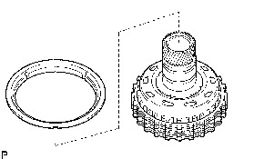
35. INSTALL REVERSE CLUTCH FLANGE
(a) Install the reverse clutch flange to the reverse clutch drum sub-assembly.
36. INSTALL REVERSE CLUTCH REACTION SLEEVE
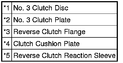
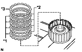
(a) Install the clutch cushion plate, reverse clutch flange, 4 No. 3 clutch discs, 3 No. 3 clutch plates and the reverse clutch reaction sleeve to the reverse clutch drum sub-assembly.
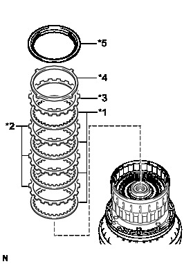
Installation order:
*1 - *2 - *1 - *2 - *1 - *2 - *1 - *3 - *4 - *5
NOTICE:
Make sure that the discs, plates, flange, sleeve and the cushion plate are installed in the correct order.
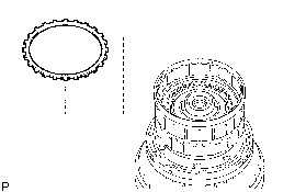
(b) Using a screwdriver, install the snap ring to the reverse clutch piston sub-assembly.
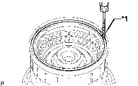

NOTICE:
Be careful not to damage the reverse clutch piston sub-assembly.
HINT
Tape the screwdriver tip before use.
37. INSPECT PACK CLEARANCE OF NO. 3 CLUTCH Transaxle Unit
38. REMOVE REVERSE CLUTCH REACTION SLEEVE
(a) Using a screwdriver, remove the snap ring from the reverse clutch piston sub-assembly.

NOTICE:
Be careful not to damage the reverse clutch piston sub-assembly.
HINT
Tape the screwdriver tip before use.
(b) Remove the reverse clutch reaction sleeve, clutch cushion plate, reverse clutch flange, 4 No. 3 clutch discs and the 3 No. 3 clutch plates from the reverse clutch drum sub-assembly.
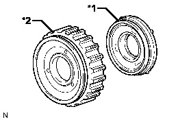
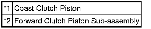
39. INSTALL FORWARD CLUTCH PISTON SUB-ASSEMBLY
(a) Install the coast clutch piston to the forward clutch piston sub-assembly.
(b) Coat a new O-ring with ATF, and install it to the input shaft.
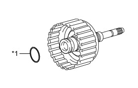

(c) Install the forward clutch piston sub-assembly to the input shaft.
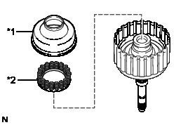
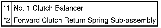
40. INSTALL NO. 1 CLUTCH BALANCER
(a) Coat a new D-ring with ATF, and install it to the No. 1 clutch balancer.
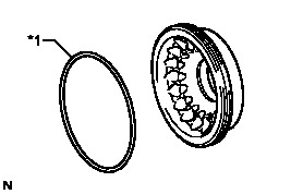

(b) Install the No. 1 clutch balancer and the forward clutch return spring sub-assembly to the input shaft.
NOTICE:
Be careful not to damage the D-ring.
(c) Place SST on the No. 1 clutch balancer, and compress the forward clutch return spring sub-assembly with a press.
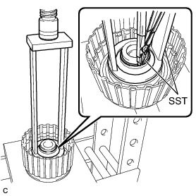
SST : 09387-00110
NOTICE:
Stop pressing when the spring sheet is lowered to the place 1 to 2 mm (0.0394 to 0.0787 in.) from the snap ring groove to prevent the spring sheet from being deformed.
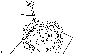
(d) Using SST, Install the snap ring.
SST : 09350-30020
09350-07070
NOTICE:
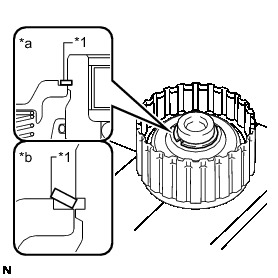
* Be sure that the end gap of the snap ring is not aligned with the spring retainer claw.
* Do not expand the snap ring excessively.
(e) Set the end gap of the snap ring in the No. 1 clutch balancer as shown in the illustration.
41. INSTALL NO. 4 CLUTCH DISC (COAST CLUTCH DISC)
(a) Install the coast clutch flange, 4 No. 4 clutch discs and the 4 No. 4 clutch plates to the forward clutch piston sub-assembly.
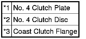
Installation order:
*1 - *2 - *1 - *2 - *1 - *2 - *1 - *2 - *3
NOTICE:
Make sure that the discs, plates and the flange are installed in the correct order.
(b) Using a screwdriver, install the snap ring.
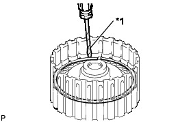

NOTICE:
Be careful not to damage the forward clutch piston sub-assembly.
HINT
Tape the screwdriver tip before use.
42. INSPECT PACK CLEARANCE OF NO. 4 CLUTCH Transaxle Unit
43. INSTALL NO. 1 CLUTCH DISC (FORWARD CLUTCH DISC)
(a) Install the forward clutch flange, 4 No. 1 clutch discs, 4 No. 1 clutch plates and the clutch cushion plate to the input shaft.
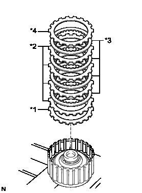
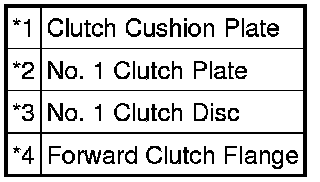
Installation order:
*1 - *2 - *3 - *2 - *3 - *2 - *3 - *2 - *3 - *4
NOTICE:
Make sure that the discs, plates, flange and the cushion plate are installed in the correct order.
(b) Using a screwdriver, install the snap ring.

NOTICE:
Be careful not to damage the input shaft.
HINT
Tape the screwdriver tip before use.
44. INSPECT PACK CLEARANCE OF NO. 1 CLUTCH Transaxle Unit
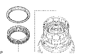
45. INSTALL CLUTCH DRUM OIL SEAL RING
(a) Coat 4 new clutch drum oil seal rings with ATF.
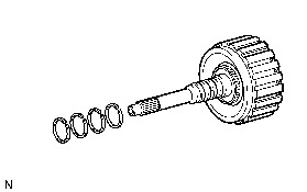
(b) Squeeze the ends of the 4 clutch drum oil seal rings together, and install them to the input shaft groove.
NOTICE:
Do not expand the ring ends excessively.
HINT
After installing the clutch drum oil seal rings, check that they rotate smoothly.
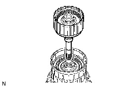
46. INSTALL INPUT SHAFT
(a) Install the input shaft to the reverse clutch drum sub-assembly.
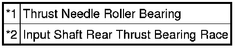
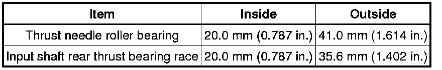
(b) Install the input shaft rear thrust bearing race and the thrust needle roller bearing to the input shaft.
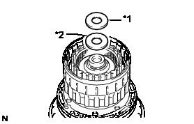
Bearing and Race Diameter
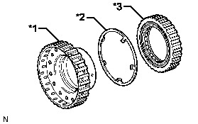
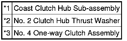
47. INSTALL NO. 4 ONE-WAY CLUTCH ASSEMBLY
(a) Install the No. 2 clutch hub thrust washer and the No. 4 one-way clutch assembly to the coast clutch hub sub-assembly.
48. INSTALL COAST CLUTCH HUB SUB-ASSEMBLY
(a) Install the coast clutch hub sub-assembly to the reverse clutch drum sub-assembly.
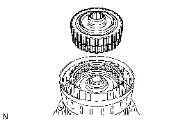
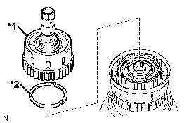
49. INSTALL FORWARD CLUTCH HUB SUB-ASSEMBLY
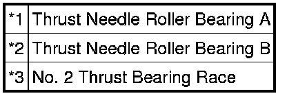
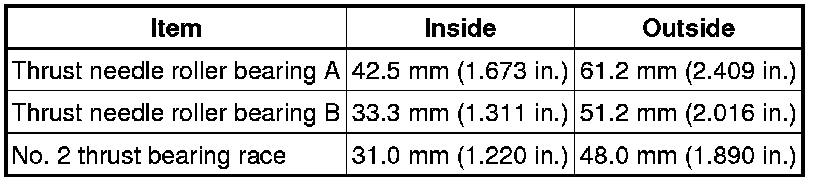
(a) Install the 2 thrust needle roller bearings and the No. 2 thrust bearing race to the forward clutch hub sub-assembly.
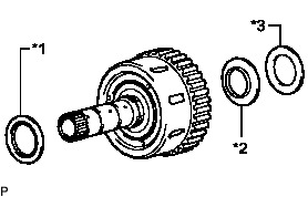
Bearing and Race Diameter
(b) Install the No. 3 clutch hub thrust washer and the forward clutch hub sub-assembly to the reverse clutch drum sub-assembly.
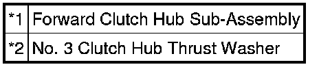
50. INSTALL NO. 3 CLUTCH DISC (REAR CLUTCH DISC)
(a) Install the clutch cushion plate, reverse clutch flange, 4 No. 3 clutch discs and the 3 No. 3 clutch plates to the reverse clutch hub sub-assembly.
Installation order:
*1 - *2 - *1 - *2 - *1 - *2 - *1 - *3 - *4
NOTICE:
Make sure that the discs, plates, flange and the cushion plate are installed in the correct order.
51. INSTALL REVERSE CLUTCH REACTION SLEEVE
(a) Install the reverse clutch reaction sleeve to the reverse clutch hub sub-assembly.