Part 5
TX6A AUTOMATIC TRANSMISSION / TRANSAXLE: AUTOMATIC TRANSMISSION UNIT: REASSEMBLY; 2013 MY FR-S [03/2012 -] (Continued)
69. INSTALL TRANSMISSION VALVE BODY ASSEMBLY
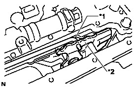
(a) Connect the manual valve connecting rod sub-assembly to the manual valve lever sub-assembly.
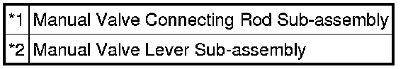
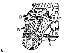
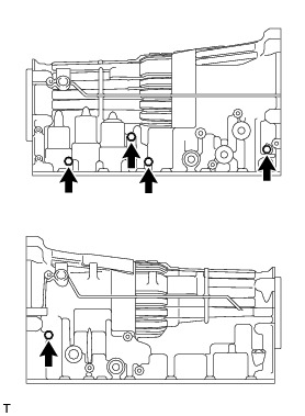
(b) Install the transmission valve body assembly to the automatic transmission case sub-assembly with the 19 bolts.
Torque : 11 Nm (112 kgf-cm, 8 ft-lbf)
HINT
Each bolt length is indicated below.
Bolt length:
Bolt A
25 mm (0.984 in.)
Bolt B
36 mm (1.42 in.)
Bolt C
45 mm (1.77 in.)
Bolt D
50 mm (1.97 in.)
(c) Install the detent spring and the detent spring cover to the transmission valve body assembly with the bolt.
Torque : 10 Nm (102 kgf-cm, 7 ft-lbf)
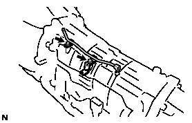
70. INSTALL TRANSMISSION WIRE
(a) Coat a new O-ring with ATF, and install it to the transmission wire.
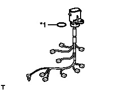

(b) Install the transmission wire with the bolt.
Torque : 5.4 Nm (55 kgf-cm, 48 in-lbf)
(c) Connect the 9 solenoid valve connectors.
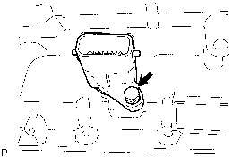
(d) Coat the ATF temperature sensor O-ring with ATF.
(e) Install the ATF temperature sensor and the temperature sensor clamp with the bolt.
Torque : 10 Nm (102 kgf-cm, 7 ft-lbf)
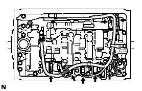
(f) Install the valve body wire harness clamp with the 2 bolt.
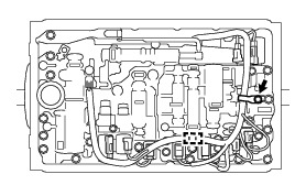
Torque : 6.4 Nm (65 kgf-cm, 57 in-lbf)
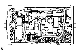
(g) Engage the wire harness clamp.
71. INSTALL VALVE BODY OIL STRAINER ASSEMBLY
(a) Coat a new O-ring with ATF, and install it to the valve body oil strainer assembly.
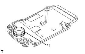

(b) Install the valve body oil strainer assembly to the transmission valve body assembly with the 4 bolts.
Torque : 10 Nm (102 kgf-cm, 7 ft-lbf)
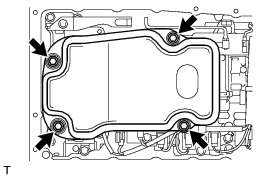
72. INSTALL AUTOMATIC TRANSMISSION OIL PAN SUB-ASSEMBLY
(a) Install the 3 transmission oil cleaner magnets to the automatic transmission oil pan sub-assembly.


(b) Install a new automatic transmission oil pan gasket and the automatic transmission oil pan sub-assembly with the 20 bolts.

Torque : 7.0 Nm (71 kgf-cm, 62 in-lbf)
(c) Install the drain plug and a new gasket.
Torque : 20 Nm (204 kgf-cm, 15 ft-lbf)
(d) Using a socket hexagon wrench 5 mm, install the overflow plug and a new gasket.
Torque : 20 Nm (204 kgf-cm, 15 ft-lbf)
73. INSTALL OUTPUT SHAFT THRUST BEARING
(a) Install the output shaft thrust bearing race, output shaft thrust bearing and the rear output shaft thrust bearing race to the output shaft of the rear planetary gear assembly.
Bearing and Race Diameter
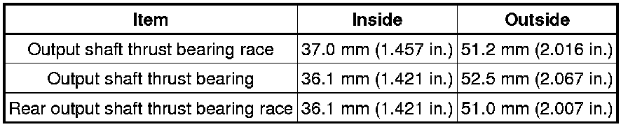
(b) Using a snap ring expander, install the snap ring.
(c) Using a feeler gauge, measure the clearance between the snap ring and the rear output shaft thrust bearing race.
Standard clearance:
0.02 to 0.12 mm (0.000787 to 0.00472 in.)
If the clearance is outside the standard range, select another rear output shaft thrust bearing race that brings the clearance within the standard range.
HINT
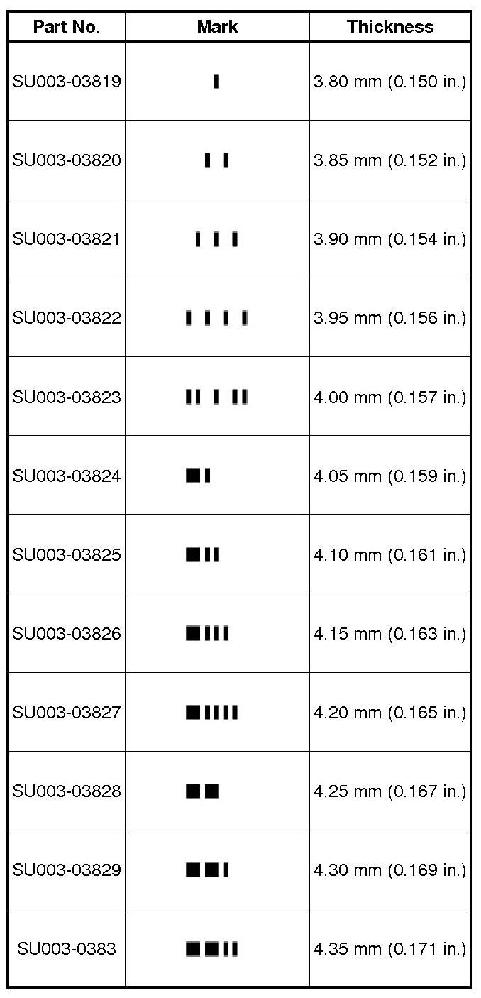
There are 12 different thicknesses for the rear output shaft thrust bearing race.
Race Thickness
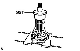
74. INSTALL AUTOMATIC TRANSMISSION EXTENSION HOUSING OIL SEAL
(a) Using SST and a hammer, drive in the automatic transmission extension housing oil seal to the extension housing sub-assembly.
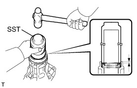
SST : 09309-37010
Drive in depth:
5.4 to 5.8 mm (0.213 to 0.228 in.)
(b) Coat the lip of a new automatic transmission extension housing oil seal with MP grease.
75. INSTALL EXTENSION HOUSING DUST DEFLECTOR
(a) Using SST and a press, install a new extension housing dust deflector to the extension housing sub-assembly.
SST : 09950-60020
09951-01030
76. INSTALL TRANSMISSION CASE ADAPTER RADIAL BALL BEARING
(a) Install the transmission case adapter radial ball bearing to the extension housing sub-assembly.
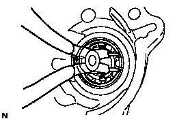
(b) Using snap ring pliers, install the snap ring to the extension housing sub-assembly.
77. INSTALL EXTENSION HOUSING SUB-ASSEMBLY
(a) Clean and degrease the threads of the 6 bolts and the contact surfaces of the case and the housing with non-residue solvent.
(b) Apply seal packing to the extension housing sub-assembly as shown in the illustration.
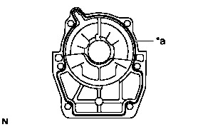
Seal packing:
Toyota Genuine Seal Packing 1281, Three Bond 1281 or equivalent
NOTICE:
Assemble the extension housing sub-assembly within 10 minutes after the seal packing application.
(c) Apply adhesive to 2 or 3 threads on the end of the 6 bolts.


Adhesive:
Toyota Genuine Adhesive 1344, Three Bond 1344 or equivalent
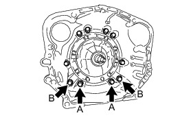
(d) Install the extension housing sub-assembly to the automatic transmission case sub-assembly with the 6 bolts.
Torque : 34 Nm (345 kgf-cm, 25 ft-lbf)
HINT
Each bolt length is indicated below.
Bolt length:
for Bolt A
35 mm (1.378 in.)
for Bolt B
45 mm (1.772 in.)
78. INSTALL AUTOMATIC TRANSMISSION HOUSING
(a) Clean and degrease the bolts and the bolt holes with non-residue solvent.
(b) Install the automatic transmission housing to the automatic transmission case sub-assembly with the 6 bolts.
Torque : 34 Nm (345 kgf-cm, 25 ft-lbf)
(c) Apply adhesive to 2 or 3 threads on the end of the 4 bolts.

Adhesive:
Toyota Genuine Adhesive 1344, Three Bond 1344 or equivalent
(d) Install the automatic transmission housing to the automatic transmission case sub-assembly with the 4 bolts.
Bolt A (M10 bolt) - Torque : 34 Nm (345 kgf-cm, 25 ft-lbf)
Bolt B (M12 bolt) - Torque : 57 Nm (579 kgf-cm, 42 ft-lbf)
79. INSTALL AUTOMATIC TRANSMISSION CASE PLUG
(a) Coat a new O-ring with ATF, and install it to the automatic transmission case plug.
(b) Using "TORX" socket wrench T55, install the automatic transmission case plug to the automatic transmission case sub-assembly.
Torque : 39 Nm (400 kgf-cm, 29 ft-lbf)
(c) Coat 5 new O-ring with ATF, and install it to the 5 automatic transmission case plug.
(d) Install the 5 automatic transmission case plugs to the automatic transmission case sub-assembly.
Torque : 7.4 Nm (75 kgf-cm, 65 in-lbf)
80. INSTALL AUTOMATIC TRANSMISSION BREATHER TUBE
(a) Install the automatic transmission breather tube to the automatic transmission case sub-assembly with the 2 bolts.
Torque : 5.4 Nm (55 kgf-cm, 48 in-lbf)
81. INSTALL TRANSMISSION REVOLUTION SENSOR
(a) Coat 2 new O-rings with ATF, and install them to the 2 transmission revolution sensors.
(b) Install the 2 transmission revolution sensors to the automatic transmission case sub-assembly with the 2 bolts.
Torque : 5.4 Nm (55 kgf-cm, 48 in-lbf)
82. INSTALL OIL COOLER TUBE ELBOW
(a) Coat 2 new O-rings with ATF, and install the 2 oil cooler tube unions.
(b) Install the 2 oil cooler tube unions to the automatic transmission case sub-assembly.
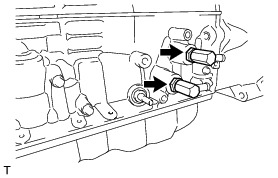
Torque : 39 Nm (393 kgf-cm, 28 ft-lbf)
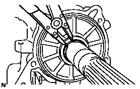
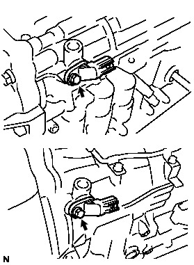
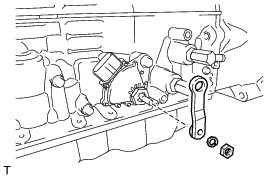
83. INSTALL PARK/NEUTRAL POSITION SWITCH ASSEMBLY
(a) Clean the bolt and the bolt hole.
(b) Apply adhesive to 2 or 3 threads on the end of the bolt.

Adhesive:
Toyota Genuine Adhesive 1344, Three Bond 1344 or equivalent
(c) Temporarily install the park/neutral position switch assembly to the automatic transmission case sub-assembly with the bolt.
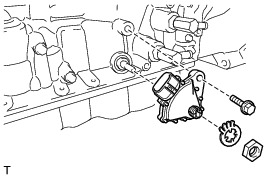
(d) Install a new lock washer and the nut.
Torque : 6.9 Nm (70 kgf-cm, 61 in-lbf)
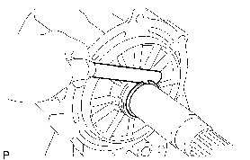
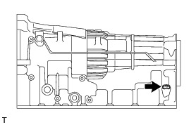
(e) Turn the transmission control shaft lever RH counterclockwise until it stops, and turn it clockwise 2 notches to set it to the N position.
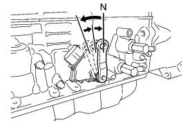
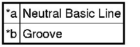
(f) Align the neutral basic line with the groove as shown in the illustration, and tighten the bolt.

Torque : 13 Nm (130 kgf-cm, 9 ft-lbf)
(g) Using a screwdriver, bend the tabs of the lock washer.
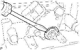
84. INSTALL TRANSMISSION CONTROL SHAFT LEVER RH
(a) Install the transmission control shaft lever RH to the park/ neutral position switch assembly with the spring washer and nut.
Torque : 16 Nm (160 kgf-cm, 12 ft-lbf)
85. INSTALL REFILL PLUG
(a) Coat a new O-ring with ATF, and install it to the refill plug.
(b) Install the refill plug.
Torque : 39 Nm (400 kgf-cm, 29 ft-lbf)