Installation
TX6A AUTOMATIC TRANSMISSION / TRANSAXLE: AUTOMATIC TRANSMISSION ASSEMBLY: INSTALLATION; 2013 MY FR-S [03/2012 -]
1. INSTALL TORQUE CONVERTER ASSEMBLY
(a) Engage the splines of the input shaft and turbine runner.
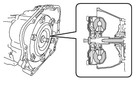
(b) Engage the splines of the stator shaft and stator while turning the torque converter assembly.
HINT
If the stator shaft splines are difficult to engage with the stator splines, move the torque converter back approximately 10 mm (0.394 in.) and engage the splines while rotating the torque converter assembly.
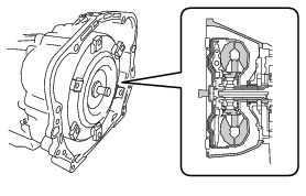
(c) Turn the torque converter assembly to engage the key of the oil pump drive gear into the slot on the torque converter assembly.
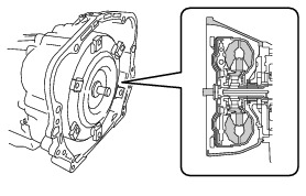
(d) Using a vernier caliper and straightedge, measure dimension A between the transmission contact surface of the engine and the torque converter contact surface of the drive plate.
(e) Using a vernier caliper and straightedge, measure dimension B shown in the illustration and check that dimension B is more than dimension A, which was measured in the first step.
Standard::
B = A + 1 mm (0.0394 in.) or more
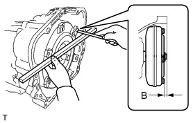
NOTICE:
* Make sure to deduct the thickness of the straightedge.
* If the transmission is installed to the engine with the torque converter not sufficiently inserted, the torque converter may be damaged.
2. INSTALL OIL COOLER TUBE
(a) Install the oil cooler tube with the bolt to the automatic transmission assembly.
Torque : 21 Nm (214 kgf-cm, 16 ft-lbf)
(b) Connect the 2 new water by-pass hoses to the transmission oil cooler with the 4 hose clamps.
3. INSTALL WIRE HARNESS
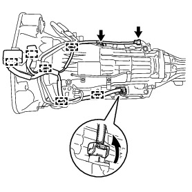
(a) Install the wire harness to the automatic transmission assembly with engage the 6 wire harness clamps.
(b) Connect the park/neutral position switch connector, transmission wire connector and the transmission revolution sensor connector.
HINT
Push up the lever until the claw of the transmission wire connector makes a connection sound.
4. INSTALL REAR NO. 1 ENGINE MOUNTING INSULATOR
(a) Install the rear No. 1 engine mounting insulator to the automatic transmission assembly with the 4 bolts.
Torque : 40 Nm (408 kgf-cm, 30 ft-lbf)
5. INSTALL AUTOMATIC TRANSMISSION ASSEMBLY
(a) Confirm that 2 knock pins are on the automatic transmission assembly contact surface of the engine cylinder block before automatic transmission assembly installation.
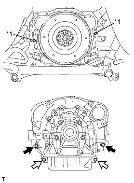
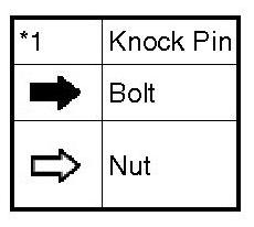
(b) Keeping the engine assembly and the automatic transmission assembly in a horizontal position, align the knock pins with each hole on the automatic transmission assembly and install the 2 bolts and 2nuts.
Torque : 50 Nm (510 kgf-cm, 37 ft-lbf)
NOTICE:
* Make sure not to pinch or damage any wire harness.
* Make sure the knock pin is fully engaged with the knock pin hole.
* Do not forcibly pry the automatic transmission assembly.
* After installing the automatic transmission assembly, confirm that the torque converter assembly can be rotated by hand.
6. INSTALL REAR NO. 2 ENGINE MOUNTING INSULATOR
(a) Install the rear No. 2 engine mounting insulator to the rear No. 1 engine mounting insulator with 2 washers and 2 nuts.
Torque : 40 Nm (408 kgf-cm, 30 ft-lbf)
(b) Install the rear No. 2 engine mounting insulator to the body with the 4 bolts.
Torque : 65 Nm (663 kgf-cm, 48 ft-lbf)
7. INSTALL EXHAUST PIPE BRACKET
(a) Install the exhaust pipe bracket with the 2 bolts.
Torque : 21 Nm (214 kgf-cm, 16 ft-lbf)
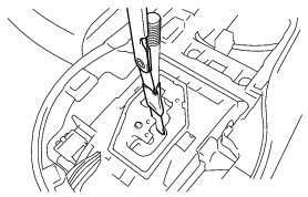
8. INSTALL FLOOR SHIFT GEAR SHIFTING ROD SUB-ASSEMBLY
(a) Apply MP grease to the pin.
(b) Install the floor shift gear shifting rod sub-assembly to the transmission control shaft lever RH with the pin and a clip.
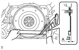
(c) While pushing the shift lock release button, move the shift lever to N.
(d) Using tape, hold a 0.3 mm feeler gauge on the floor shift control select lever.
(e) Using tape, attach the floor shift control select lever to the console box assembly.
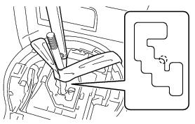
NOTICE:
Make sure that the feeler gauge is not on the area shown in the illustration.
(f) Turn the transmission control shaft lever RH of the park/neutral position switch assembly counterclockwise until it stops, and turn it clockwise 2 notches to set it to the N position.

(g) Temporarily install the floor shift gear shifting rod sub-assembly with the nut.
(h) Tighten the nut while lightly pushing the lever rearward.
Torque : 18 Nm (184 kgf-cm, 13 ft-lbf)
NOTICE:
Do not push the lever too hard.
9. INSTALL TRANSMISSION REVOLUTION SENSOR (NT) Installation
10. CONNECT OIL COOLER TUBE
(a) Fasten the oil cooler pipe with the oil cooler tube using 2 bolts.
Torque : 21 Nm (214 kgf-cm, 16 ft-lbf)
11. INSTALL TRANSMISSION OIL COOLER HOSE
(a) Install the 2 new transmission oil cooler hoses to the transmission oil cooler with the 4 hose clamps.
12. INSTALL EXHAUST MANIFOLD
Installation
13. CONNECT AUTOMATIC TRANSMISSION ASSEMBLY
(a) Install the 2 bolts to the automatic transmission assembly.
Torque : 50 Nm (510 kgf-cm, 37 ft-lbf)
14. INSTALL DRIVE PLATE AND TORQUE CONVERTER SETTING BOLT
(a) Install the 6 drive plate and torque converter setting bolt.
Torque : 25 Nm (255 kgf-cm, 18 ft-lbf)
NOTICE:
* Make sure that the drive plate and torque converter setting bolts do not fall into the clutch housing.
* Make sure not to damage the drive plate and torque converter setting bolts.
15. INSTALL FLYWHEEL HOUSING UNDER COVER
(a) Install the flywheel housing side cover.
16. CONNECT VACUUM TUBE CONNECTOR HOSE
(a) Connect the vacuum tube connector hose with the 2 bolts.
Torque : 18 Nm (184 kgf-cm, 13 ft-lbf)
17. CONNECT WIRE HARNESS
(a) Install the No. 2 engine hanger with the 2 bolts.
Torque : 21 Nm (214 kgf-cm, 16 ft-lbf)
(b) Install the wire harness clamp bracket with the bolt.
Torque : 10 Nm (102 kgf-cm, 7 ft-lbf)
(c) Engage the wire harness clamp.
(d) Connect the 3 connectors.
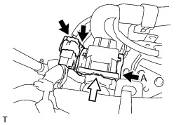
HINT
Push down the lever until the claw of the connector (A) makes a connection sound.
(e) Engage the 4 wire harness clamps.
(f) Install the ground cable to the automatic transmission assembly with the bolt
Torque : 13 Nm (133 kgf-cm, 10 ft-lbf)
(g) Connect the 2 connectors.
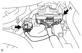
HINT
Push down the lever until the claw of the connector (A) makes a connection sound.
18. INSTALL STARTER ASSEMBLY
Installation
19. INSTALL FRONT STABILIZER BAR
Installation
20. INSTALL PROPELLER WITH CENTER BEARING SHAFT ASSEMBLY
Installation
21. INSTALL NO. 2 ENGINE UNDER COVER Installation
22. INSTALL NO. 1 ENGINE UNDER COVER Installation
23. CONNECT BATTERY NEGATIVE TERMINAL Installation
24. ADD ENGINE COOLANT
25. ADD AUTOMATIC TRANSMISSION FLUID
Adjustment
26. CHECK FOR ENGINE COOLANT LEAKS Testing and Inspection
27. INSPECT SHIFT LEVER POSITION Initial Inspection and Diagnostic Overview
28. CHECK FOR EXHAUST GAS LEAKS Installation
29. RESET CHECK RESET MEMORY
Programming and Relearning