Transaxle Unit
TX6A AUTOMATIC TRANSMISSION / TRANSAXLE: AUTOMATIC TRANSMISSION UNIT: INSPECTION; 2013 MY FR-S [03/2012 -]
1. INSPECT 1ST AND REVERSE BRAKE RETURN SPRING SUB-ASSEMBLY
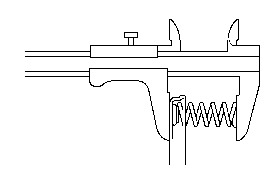
(a) Using a vernier caliper, measure the free length of the spring together with the spring seat.
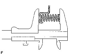
Standard free length:
23.74 mm (0.935 in.)
If the free length is shorter than the standard free length, replace the 1st and reverse brake return spring sub-assembly.
2. INSPECT REAR PLANETARY GEAR ASSEMBLY
(a) Using a feeler gauge, measure the rear planetary gear pinion thrust clearance.
Standard clearance:
0.2 to 0.6 mm (0.00788 to 0.0236 in.)
If the clearance is more than the standard clearance, replace the rear planetary gear assembly.
(b) Using a caliper gauge, measure the inside diameter of the rear planetary gear bushing.
Standard inside diameter:
18.025 mm (0.710 in.)
If the inside diameter is more than the standard inside diameter, replace the rear planetary gear assembly.
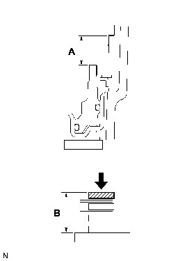
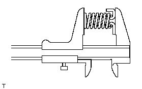
3. INSPECT PACK CLEARANCE OF NO. 4 BRAKE
(a) Make sure that the 1st and reverse brake piston moves smoothly when applying and releasing compressed air (392 kPa, 4.0 kgf/cm2, 57 psi).
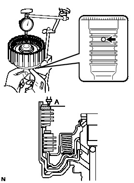
(b) Using a vernier caliper, measure the level difference (dimension A) between the upper surface of the brake apply tube and the contact surface of the No. 4 brake flange at both ends across the 1st and reverse brake piston diameter, and calculate the average.
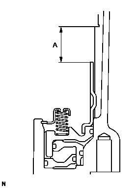
NOTICE:
The 1st and reverse brake piston must be securely installed to the end face of the transmission case.
HINT
Dimension A = 23.32 to 24.18 mm (0.919 to 0.951 in.)
(c) Using a vernier caliper, and while applying compression of 4.9 N (0.5 kgf, 1.1 lbf) or less, measure the thickness (dimension B) of the 2 No. 4 brake flanges, 4 No. 4 brake plates and the 5 No. 4 brake discs altogether at both ends across a diameter, and calculate the average.
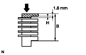
HINT
Dimension B = 23.64 to 26.00 mm (0.931 to 1.023 in.)
Pack clearance = Dimension A - Dimension B - 0.18 mm (0.00709 in.) + 1.8 mm (0.0709 in.)
Pack clearance:
0.5 to 0.8 mm (0.0197 to 0.0314 in.)
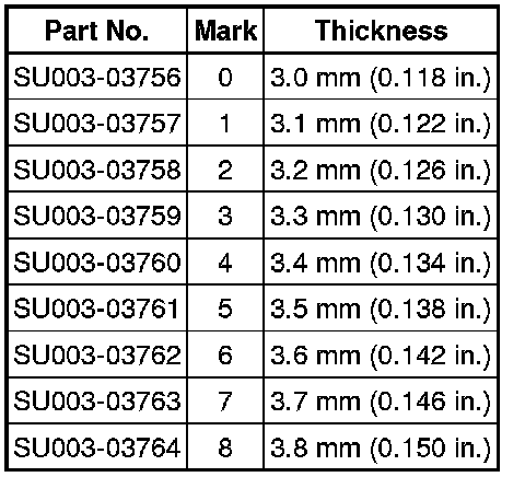
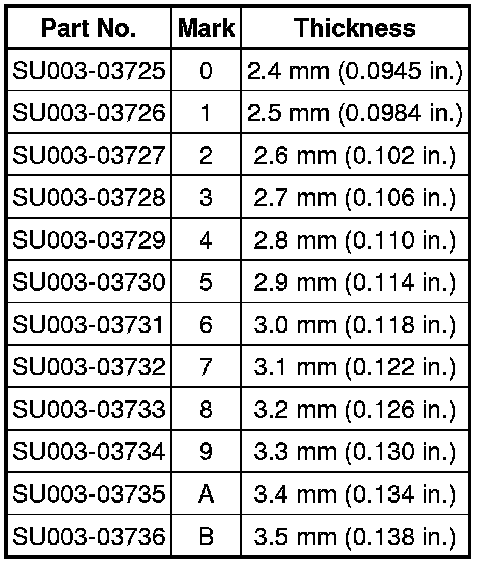
(d) If the pack clearance is outside the standard range, select and install a No. 4 brake flange that brings the pack clearance to be within the standard range.
HINT
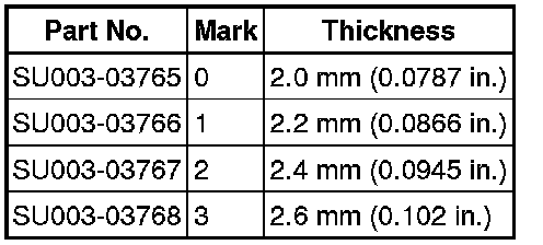
There are 8 types of No. 4 brake flanges that can be used to adjust the pack clearance. Select the one with the most appropriate thickness.
Thickness H:
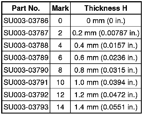
4. INSPECT NO. 4 BRAKE DISC
(a) Check whether the sliding surfaces of the discs, plates and the flanges are worn or burnt.
If necessary, replace them.
NOTICE:
* If the linings of the discs are peeled off or discolored, or if any part of the printed numbers is damaged, replace all the discs.
* Before assembling new discs, soak them in ATF for at least 15 minutes.
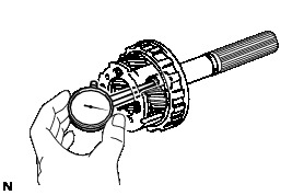
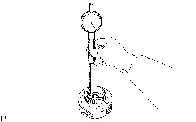
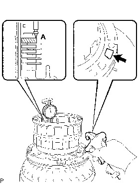
5. INSPECT INTERMEDIATE SHAFT
(a) Using a dial indicator, check the intermediate shaft runout.
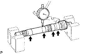
Standard runout:
0.03 mm (0.00118 in.)
If the runout is more than the standard, replace the intermediate shaft with a new one.
(b) Using a micrometer, check the outer diameter of the intermediate shaft at each point shown in the illustration.
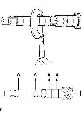
Standard diameter:
A
22.962 to 22.975 mm (0.9041 to 0.9045 in.)
B
27.759 to 27.775 mm (1.0929 to 1.0935 in.)
If the outer diameter is less than the standard, replace the intermediate shaft with a new one.
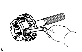
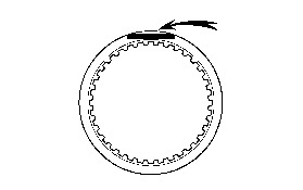
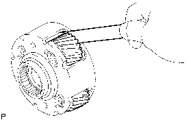
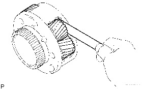
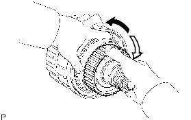
6. INSPECT NO. 3 ONE-WAY CLUTCH ASSEMBLY
(a) Hold the rear planetary ring gear flange sub-assembly and turn the No. 3 one-way clutch assembly.
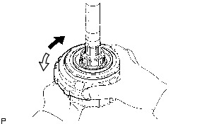
(b) Check that the No. 3 one-way clutch assembly turns freely when turned counterclockwise and locks when turned clockwise.
If there is a problem with the No. 3 one-way clutch assembly, replace it.
7. INSPECT CENTER PLANETARY GEAR ASSEMBLY
(a) Using a feeler gauge, measure the center planetary gear pinion thrust clearance.
Standard clearance:
0.12 to 0.68 mm (0.00473 to 0.0267 in.)
If the clearance is more than the standard clearance, replace the center planetary gear assembly.
8. INSPECT NO. 2 BRAKE DISC
(a) Check whether the sliding surfaces of the discs, plates and the flanges are worn or burnt.
If necessary, replace them.
NOTICE:
* If the linings of the discs are peeled off or discolored, or if any part of the printed numbers is damaged, replace all the discs.
* Before assembling new discs, soak them in ATF for at least 15 minutes.
9. INSPECT NO. 2 BRAKE PISTON RETURN SPRING SUB-ASSEMBLY
(a) Using a vernier caliper, measure the free length of the spring together with the spring seat.
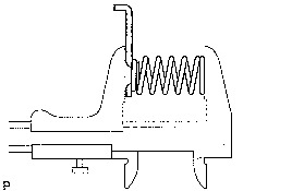
Standard free length:
22.66 mm (0.892 in.)
If the free length is shorter than the standard free length, replace the No. 2 brake piston return spring sub-assembly.
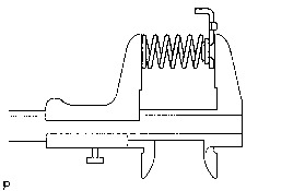
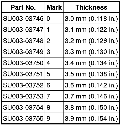
10. INSPECT PISTON STROKE OF NO. 2 BRAKE PISTON
(a) Make sure that the No. 2 brake piston moves smoothly when applying and releasing compressed air (392 kPa, 4.0 kgf/cm2, 57 psi).

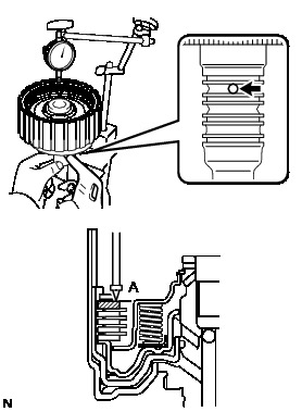
(b) Using SST and a dial indicator, measure the moving distance (distance A) of the No. 2 brake disc at both ends across a diameter while blowing air (392 kPa, 4.0 kgf/cm2, 57 psi) into the oil hole as shown in the illustration, and calculate the average.
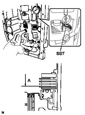
SST : 09350-30020
09350-06120
Piston stroke:
0.6 to 0.9 mm (0.0237 to 0.0354 in.)
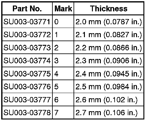
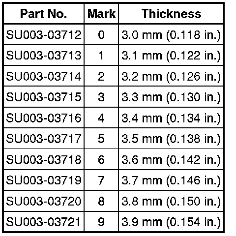
(c) If the piston stroke is outside the standard range, select and install a No. 2 brake flange that brings the piston stroke within the standard range.
HINT
There are 8 types of No. 2 brake flanges that can be used to adjust the piston stroke. Select one with the most appropriate thickness.
Flange Thickness:
11. INSPECT BRAKE PISTON RETURN SPRING SUB-ASSEMBLY
(a) Using a vernier caliper, measure the free length of the spring together with the spring seat.
Standard free length:
17.05 mm (0.671 in.)
If the free length is shorter than the standard free length, replace the brake piston return spring sub-assembly.
12. INSPECT FRONT PLANETARY GEAR ASSEMBLY
(a) Using a feeler gauge, measure the front planetary gear pinion thrust clearance.
Standard clearance:
0.20 to 0.60 mm (0.00788 to 0.0236 in.)
If the clearance is more than the standard clearance, replace the front planetary gear assembly.
(b) Using a cylinder gauge, measure the inside diameter of the front planetary gear bushing.
Standard inside diameter:
48.78 mm (1.92 in.)
If the inside diameter is more than the standard inside diameter, replace the front planetary gear assembly.
13. INSPECT ONE-WAY CLUTCH ASSEMBLY
(a) Install the one-way clutch assembly to the one-way clutch inner race sub-assembly.
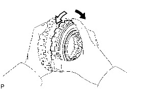

(b) Hold the one-way clutch inner race sub-assembly and turn the one-way clutch assembly.
(c) Check that the one-way clutch assembly turns freely when turned counterclockwise and locks when turned clockwise.
If there is a problem with the one-way clutch assembly, replace it.
(d) Remove the one-way clutch assembly from the one-way clutch inner race sub-assembly.
14. INSPECT PISTON STROKE OF NO. 1 BRAKE PISTON
(a) Make sure that the No. 1 brake piston moves smoothly when applying and releasing compressed air (392 kPa, 4.0 kgf/cm2, 57 psi).
(b) Using a vernier caliper, and while applying compression of 4.9 N (0.5 kgf, 1.1 lbf) or less, measure the level difference (dimension A) between the upper surface of the No. 1 brake piston and the contact surface of the No. 1 brake flange at both ends across the No. 1 brake piston diameter.
(c) Using a vernier caliper, measure the thickness (dimension B) of the No. 1 brake flange, 3 No. 1 brake plates and the 3 No. 1 brake discs altogether at both ends across a diameter, and calculate the average.
HINT
Dimension A = 15.27 to 15.92 mm (0.602 to 0.626 in.)
Dimension B = 14.50 to 15.54 mm (0.571 to 0.611 in.)
Piston stroke = Dimension A - Dimension B
Piston stroke:
0.42 to 0.72 mm (0.0166 to 0.0283 in.)
(d) If the piston stroke is outside the standard range, parts may have been assembled incorrectly, so check and reassemble them again.
(e) If the piston stroke is still outside the standard range, select another No. 1 brake flange that brings the piston stroke within the standard range.
HINT
There are 4 types of No. 1 brake flanges that can be used to adjust the piston stroke. Select one with the most appropriate thickness.
Flange Thickness:
15. INSPECT NO. 1 BRAKE DISC
(a) Check whether the sliding surfaces of the discs, plates and the flange are worn or burnt.
If necessary, replace them.
NOTICE:
* If the linings of the discs are peeled off or discolored, or if any part of the groove is damaged, replace all the discs.
* Before assembling new discs, soak them in ATF for at least 15 minutes.
16. INSPECT NO. 3 BRAKE PISTON RETURN SPRING SUB-ASSEMBLY
(a) Using a vernier caliper, measure the free length of the spring together with the spring seat.
Standard free length:
15.72 mm (0.619 in.)
If the free length is shorter than the standard free length, replace the No. 3 brake piston return spring sub-assembly.
17. INSPECT NO. 3 BRAKE DISC (2ND BRAKE DISC SET)
(a) Check whether the sliding surfaces of the discs, plates and the flange are worn or burnt.
If necessary, replace them.
NOTICE:
* If the linings of the discs are peeled off or discolored, or if any part of the printed numbers is damaged, replace all the discs.
* Before assembling new discs, soak them in ATF for at least 15 minutes.
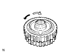
18. INSPECT NO. 2 ONE-WAY CLUTCH ASSEMBLY
(a) Hold the reverse clutch hub sub-assembly and turn the No. 2 one-way clutch assembly.

(b) Check that the No. 2 one-way clutch assembly turns freely when turned clockwise and locks when turned counterclockwise.
If there is a problem with the No. 2 one-way clutch assembly, replace it.
19. INSPECT INDIVIDUAL PISTON OPERATION
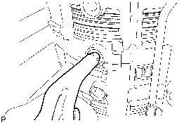
(a) Check the operating sound while applying compressed air into the oil holes indicated in the illustration.
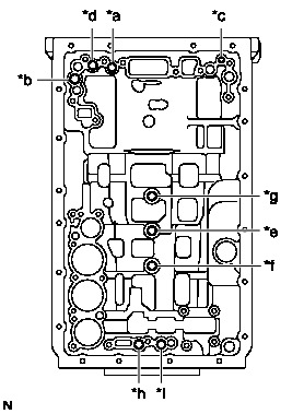
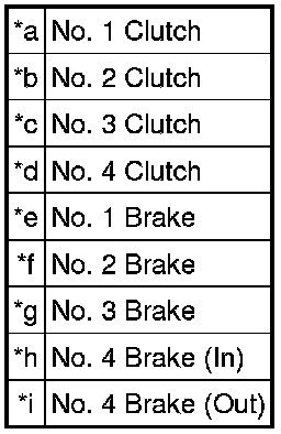
HINT
When inspecting the direct clutch, check the operating sound with the C3 accumulator piston hole closed.
If there is no sound, disassemble the parts and check the installation condition of the parts.
20. INSPECT NO. 4 ONE-WAY CLUTCH ASSEMBLY
(a) Hold the coast clutch hub sub-assembly and turn the No. 4 one-way clutch assembly.

(b) Check that the No. 4 one-way clutch assembly turns freely when turned clockwise and locks when turned counterclockwise.
If there is a problem with the No. 4 one-way clutch assembly, replace it.
21. INSPECT DIRECT CLUTCH RETURN SPRING SUB-ASSEMBLY
(a) Using a vernier caliper, measure the free length of the spring together with the spring seat.
Standard free length:
20.02 mm (0.788 in.)
If the free length is shorter than the standard free length, replace the direct clutch return spring sub-assembly.
22. INSPECT REVERSE CLUTCH RETURN SPRING SUB-ASSEMBLY
(a) Using a vernier caliper, measure the free length of the spring together with the spring seat.
Standard free length:
21.03 mm (0.828 in.)
If the free length is shorter than the standard free length, replace the reverse clutch return spring sub-assembly.
23. INSPECT NO. 2 CLUTCH DISC (DIRECT CLUTCH DISC)
(a) Check whether the sliding surfaces of the discs, plates and the flange are worn or burnt.
If necessary, replace them.
NOTICE:
* If the linings of the discs are peeled off or discolored, or even a part of the printed numbers is damaged, replace all the discs.
* Before assembling new discs, soak them in ATF for at least 15 minutes.
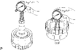
24. INSPECT PACK CLEARANCE OF NO. 2 CLUTCH
(a) Using a dial indicator, measure the moving distance (distance A) of the direct clutch flange at both ends across a diameter while blowing air (392 kPa, 4.0 kgf/cm2, 57 psi) into the oil hole as shown in the illustration, and calculate the average.
HINT
Flange moving distance A = 0.24 to 1.12 mm (0.00944 to 0.0440 in.)
Pack clearance = Flange moving distance A - 0.03 mm (0.00118 in.)
Pack clearance:
0.5 to 0.8 mm (0.0197 to 0.0314 in.)
NOTICE:
When measuring the moving distance, install a standard flange {thickness: 3.4 mm (0.134 in.)} to the position indicated by the shaded area in the illustration.
(b) If the pack clearance is outside the standard range, select and install a direct clutch flange that brings the pack clearance within the standard range.
HINT
There are 9 types of direct clutch flanges that can be used to adjust the pack clearance. Select the one with the most appropriate thickness.
Flange Thickness:
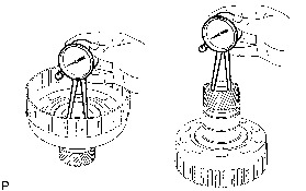
25. INSPECT PACK CLEARANCE OF NO. 3 CLUTCH
(a) Using a dial indicator, measure the reverse clutch piston stroke (distance A) and the moving distance (distance B) of the reverse clutch flange at both ends across a diameter while blowing air (392 kPa, 4.0 kgf/cm2, 57 psi) into the oil hole as shown in the illustration, and calculate the average.
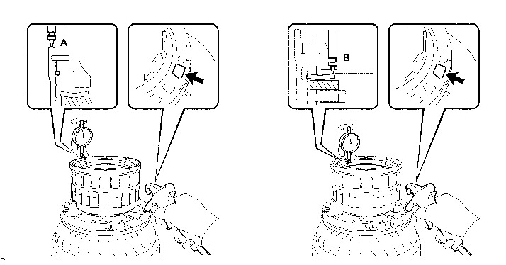
HINT
Piston stroke A = 1.62 to 2.68 mm (0.0638 to 0.105 in.)
Flange moving distance B = 1.22 to 1.67 mm (0.0481 to 0.0657 in.)
Pack clearance = Piston stroke A - Flange moving distance B - 0.02 mm (0.000787 in.)
Pack clearance:
0.4 to 0.7 mm (0.0158 to 0.0275 in.)
NOTICE:
When measuring the moving distance, install a standard flange {thickness: 2.8 mm (0.110 in.)} to the position indicated by the shaded area in the illustration.
(b) If the pack clearance is outside the standard range, select and install a reverse clutch flange that brings the pack clearance within the standard range.
HINT
There are 12 types of reverse clutch flanges that can be used to adjust the pack clearance. Select the one with the most appropriate thickness.
Flange Thickness:
26. INSPECT FORWARD CLUTCH RETURN SPRING SUB-ASSEMBLY
(a) Using a vernier caliper, measure the free length of the spring together with the spring seat.
Standard free length:
26.29 mm (1.04 in.)
If the free length is shorter than the standard free length, replace the forward clutch return spring sub-assembly.
27. INSPECT NO. 4 CLUTCH DISC (COAST CLUTCH DISC)
(a) Check whether the sliding surfaces of the discs, plates and the flange are worn or burnt.
If necessary, replace them.
NOTICE:
* If the linings of the discs are peeled off or discolored, or even a part of the printed numbers is damaged, replace all the discs.
* Before assembling new discs, soak them in ATF for at least 15 minutes.
28. INSPECT PACK CLEARANCE OF NO. 1 CLUTCH
(a) Using a dial indicator, measure the moving distance (distance A) of the forward clutch flange at both ends across a diameter while blowing air (196 kPa, 2.0 kgf/cm2, 28 psi) into the oil hole as shown in the illustration, and calculate the average.
HINT
Flange moving distance A = 0.14 to 0.17 mm (0.00552 to 0.00669 in.)
Pack clearance = Flange moving distance A - 0.01 mm (0.000394 in.)
Pack clearance:
0.56 to 0.86 mm (0.0221 to 0.0338 in.)
NOTICE:
When measuring the moving distance, install a standard flange {thickness: 3.5 mm (0.138 in.)} to the position indicated by the shaded area in the illustration.
(b) If the pack clearance is outside the standard range, select and install a forward clutch flange that brings the pack clearance within the standard range.
HINT
There are 10 types of forward clutch flanges that can be used to adjust the pack clearance. Select the one with the most appropriate thickness.
Flange Thickness:
29. INSPECT NO. 1 CLUTCH DISC (FORWARD CLUTCH DISC)
(a) Check whether the sliding surfaces of the discs, plates and the flange are worn or burnt.
If necessary, replace them.
NOTICE:
* If the linings of the discs are peeled off or discolored, or even a part of the printed numbers is damaged, replace all the discs.
* Before assembling new discs, soak them in ATF for at least 15 minutes.
30. INSPECT PACK CLEARANCE OF NO. 4 CLUTCH
(a) Using a dial indicator, measure the moving distance (distance A) of the coast clutch flange at both ends across a diameter while blowing air (196 kPa, 2.0 kgf/cm2, 28 psi) into the oil hole as shown in the illustration, and calculate the average.
HINT
Flange moving distance A = 0.02 to 1.01 mm (0.000787 to 0.0397 in.)
Pack clearance = Flange moving distance A - 0.01 mm (0.000394 in.)
Pack clearance:
0.4 to 0.7 mm (0.0158 to 0.0275 in.)
NOTICE:
When measuring the moving distance, install a standard flange {thickness: 3.5 mm (0.138 in.)} to the position indicated by the shaded area in the illustration.
(b) If the pack clearance is outside the standard range, select and install a coast clutch flange that brings the pack clearance within the standard range.
HINT
There are 10 types of coast clutch flanges that can be used to adjust the pack clearance. Select the one with the most appropriate thickness.
Flange Thickness:
31. INSPECT FORWARD CLUTCH HUB SUB-ASSEMBLY
(a) Using a caliper gauge, measure the inside diameter of the forward clutch hub bushing.
Standard inside diameter:
23.037 to 23.062 mm (0.9070 to 0.9079 in.)
If the inside diameter is more than the standard inside diameter, replace the forward clutch hub sub-assembly.
32. INSPECT NO. 3 CLUTCH DISC (REAR CLUTCH DISC)
(a) Check whether the sliding surfaces of the discs, plates and the flange are worn or burnt.
If necessary, replace them.
NOTICE:
* If the linings of the discs are peeled off or discolored, or even a part of the printed numbers is damaged, replace all the discs.
* Before assembling new discs, soak them in ATF for at least 15 minutes.
33. INSPECT REVERSE CLUTCH HUB SUB-ASSEMBLY
(a) Using a caliper gauge, measure the inside diameter of the reverse clutch hub bushing.
Standard inside diameter:
33.312 to 33.337 mm (1.3115 to 1.3124 in.)
If the inside diameter is more than the standard inside diameter, replace the reverse clutch hub sub-assembly.