Part 3
TL70 MANUAL TRANSMISSION / TRANSAXLE: MANUAL TRANSAXLE UNIT: REASSEMBLY; 2013 MY FR-S [03/2012 -] (Continued)
29. INSTALL NO. 1 EXTENSION HOUSING OIL RECEIVER PIPE
(a) Install the extension housing ring pin.

(b) Install the No. 1 extension housing oil receiver pipe and stopper plate with a new bolt.


Torque : 8.5 Nm (87 kgf-cm, 75 in-lbf)
NOTICE:
Confirm that the end of No. 1 extension housing oil receiver pipe is properly fitted in the groove.
30. INSTALL NO. 2 EXTENSION HOUSING OIL RECEIVER PIPE
(a) Install the No. 2 extension housing oil receiver pipe.

31. INSTALL MANUAL TRANSMISSION EXTENSION HOUSING OIL SEAL
(a) Apply MP grease to the lip of the new manual transmission extension housing oil seal.

(b) Using SST and a hammer, install a new manual transmission extension housing oil seal.
SST : 09325-20010
Installation depth:
0.1 to 1.1 mm (0.00394 to 0.0433 in.) (from the end surface of the manual transmission extension housing sub-assembly)
NOTICE:
Do not damage the lip of the manual transmission extension housing oil seal.
32. INSTALL EXTENSION HOUSING DUST DEFLECTOR
(a) Using SST and a hammer, install a new extension housing dust deflector.

SST : 09950-60020
09951-00750
SST : 09950-70010
09951-07100
HINT
Make sure to tap it until it touches the manual transmission extension housing sub-assembly.
33. INSTALL EXTENSION HOUSING REAR OIL SEAL
(a) Using SST and a hammer, install a new extension housing rear oil seal.

SST : 09612-70100
09612-07210
Installation depth:
1.0 to 2.0 mm (0.0394 to 0.0787 in.) (from the end surface of the manual transmission extension housing sub-assembly)
NOTICE:
Do not damage the lip of the extension housing rear oil seal.
(b) Apply MP grease to the lip of the extension housing rear oil seal.
34. INSTALL MANUAL TRANSMISSION EXTENSION HOUSING SUB-ASSEMBLY
(a) Apply seal packing 1281 continuously to the manual transmission extension housing sub-assembly as shown in the illustration.


NOTICE:
Install it within 10 minutes of the seal packing application.
(b) Install the manual transmission extension housing sub-assembly and clamp with 8 new bolts.


Torque : 29 Nm (296 kgf-cm, 21 ft-lbf)
NOTICE:
* Be sure to install the manual transmission extension housing sub-assembly while the transmission is in neutral.
* Make sure to align the knock pin with the hole securely.
(c) Install a new bolt.

Torque : 31 Nm (316 kgf-cm, 23 ft-lbf)
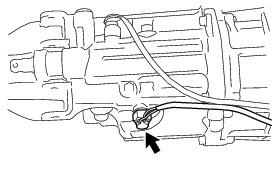
35. INSTALL NO. 2 STRAIGHT SCREW PLUG
(a) Using a 27 mm deep socket wrench, install a new No. 2 straight screw plug, shift and select lever spring and lock ball pin.

Torque : 39 Nm (400 kgf-cm, 29 ft-lbf)
36. INSTALL LOCK BALL PIN
(a) Using a 10 mm hexagon socket wrench, install a new No. 2 straight screw plug, shift and select lever spring and lock ball pin.

Torque : 25 Nm (250 kgf-cm, 18 ft-lbf)
37. INSTALL WIRE HARNESS CLAMP BRACKET
(a) Install the wire harness clamp bracket with a new bolt.
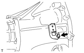
Torque : 7.0 Nm (71 kgf-cm, 62 in-lbf)
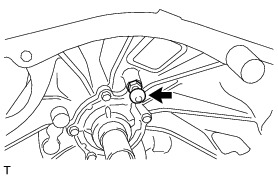
38. INSTALL NEUTRAL POSITION SWITCH ASSEMBLY
(a) Using a 19 mm union nut wrench, install the neutral position switch assembly (Connector color brown) and a new gasket.

Torque : 32 Nm (329 kgf-cm, 24 ft-lbf)
NOTICE:
Use the formula to calculate special torque values for situations where the union nut wrench is combined with a torque wrench Service Precautions.
(b) Engage the clamp and connect the neutral position switch assembly wire.

39. INSTALL BACK-UP LIGHT SWITCH ASSEMBLY
(a) Using a 19 mm union nut wrench, install the back-up light switch assembly (Connector color gray) and a new gasket.
Torque : 32 Nm (329 kgf-cm, 24 ft-lbf)
NOTICE:
Use the formula to calculate special torque values for situations where the union nut wrench is combined with a torque wrench Service Precautions.
(b) In the order indicated in the illustration, engage the 3 clamps in place, and connect the back-up light switch assembly wire and neutral position switch assembly wire.

HINT
Install the wire harness so that there is slack on the connector side.
40. INSTALL RELEASE FORK SUPPORT
(a) Using a 19 mm deep socket wrench, install the release fork support to the clutch housing.
Torque : 16 Nm (163 kgf-cm, 12 ft-lbf)
41. INSTALL MANUAL TRANSMISSION DRAIN PLUG SUB-ASSEMBLY
(a) Install the manual transmission drain plug sub-assembly with a new manual transmission drain plug gasket to the manual transmission case.
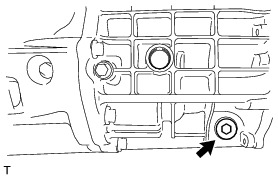
Torque : 37 Nm (377 kgf-cm, 27 ft-lbf)
42. INSTALL MANUAL TRANSMISSION FILLER PLUG
(a) Install the manual transmission filler plug with a new manual transmission filler plug gasket to the manual transmission case.

Torque : 37 Nm (377 kgf-cm, 27 ft-lbf)