Installation
TL70 MANUAL TRANSMISSION / TRANSAXLE: MANUAL TRANSMISSION ASSEMBLY: INSTALLATION; 2013 MY FR-S [03/2012 -]
1. INSTALL CONTROL SHAFT
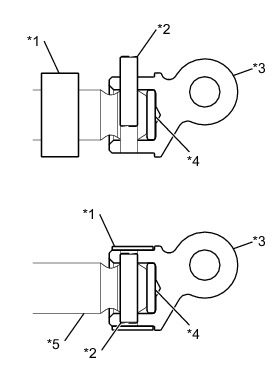
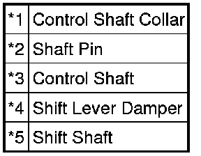
(a) Install a new control shaft collar onto the shift shaft.
(b) Install the shift lever damper and control shaft to the shift shaft.
(c) Using a pin punch (5 mm (0.197 in.)) and a hammer, align the control shaft hole and the shift shaft hole with the cutout of the control shaft collar, and insert the shaft pin from above.
(d) Slide the control shaft collar until it comes into contact with the stopper of the control shaft, then stake it to the cutout.
NOTICE:
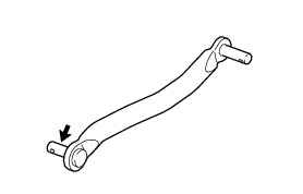
Be careful to install the floor shift control shaft in the proper direction.
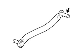
2. INSTALL FLOOR SHIFT CONTROL SHAFT
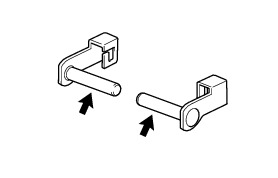
(a) Apply a light coat of with MP grease to the floor shift control shaft.

(b) Install the 2 collars to the floor shift control shaft.
(c) Install the plate washer and clip.
3. INSTALL SHIFT LEVER RETAINER BUSHING
(a) Install the 4 shift lever retainer bushings.
4. INSTALL FLOOR SHIFT CONTROL SHIFT LEVER RETAINER
(a) Apply a light coat of with MP grease to the new 2 shift lever pins.

(b) Install the floor shift control shift lever retainer with the 2 shift lever pins.
(c) Secure the shift lever pins to the extension housing sub-assembly.
5. INSTALL FLOOR SHIFT CONTROL SHIFT LEVER RETAINER SUB-ASSEMBLY
(a) Apply a light coat of with MP grease to the floor shift control shift lever retainer sub-assembly.

(b) Install the floor shift control shift lever retainer sub-assembly to the floor shift control shift lever retainer.
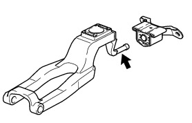
6. INSTALL REAR NO. 1 ENGINE MOUNTING INSULATOR
(a) Install the rear No. 1 engine mounting insulator to the manual transmission assembly with the 4 bolts.
Torque : 40 Nm (408 kgf-cm, 30 ft-lbf)
7. INSTALL MANUAL TRANSMISSION ASSEMBLY
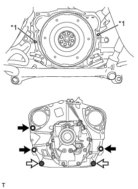
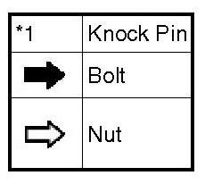
(a) Confirm that 2 knock pins are on the manual transmission assembly contact surface of the engine cylinder block before manual transmission assembly installation.
(b) Install the manual transmission assembly to the engine with the 3 bolts and 2 nuts.
Torque : 50 Nm (510 kgf-cm, 37 ft-lbf)
NOTICE:
* Do not apply excessive force to the transmission assembly as this will break the input shaft.
* Insert dowel pins into the dowel holes securely so that the end face of the transmission assembly fits close against the engine assembly before tightening the bolts.
8. INSTALL REAR NO. 2 ENGINE MOUNTING INSULATOR
(a) Tilt up the manual transmission assembly.
(b) Install the rear No. 2 engine mounting insulator to the rear No. 1 engine mounting insulator with the 2 washers and 2 nuts.
Torque : 55 Nm (561 kgf-cm, 41 ft-lbf)
(c) Install the rear No. 2 engine mounting insulator to the body with the 4 bolts.
Torque : 65 Nm (663 kgf-cm, 48 ft-lbf)
9. REMOVE EXHAUST PIPE BRACKET
(a) Install the exhaust pipe bracket with the 2 bolts.
Torque : 23 Nm (235 kgf-cm, 17 ft-lbf)
10. INSTALL FLOOR SHIFT LEVER ASSEMBLY
(a) Apply a light coat of with MP grease to the floor shift control shaft.

(b) Install the O-ring and 2 bushings to the shift lever assembly.
(c) Install the plate washer to the floor shift lever assembly.
(d) Install the shift lever assembly with the clip.
(e) Install the shift and select lever boot.
11. INSTALL SHIFT AND SELECT LEVER BOOT
(a) Install the shift and select lever boot to the floor shift control shaft.
12. INSTALL FLOOR SHIFT CONTROL SHIFT LEVER RETAINER SUB-ASSEMBLY
(a) Install the floor shift control shift lever retainer sub-assembly with the 2 bolts.
Torque : 18 Nm (184 kgf-cm, 13 ft-lbf)
13. INSTALL EXHAUST MANIFOLD
Installation
14. INSTALL MANUAL TRANSMISSION ASSEMBLY
(a) Install the bolt to the manual transmission assembly.
Torque : 50 Nm (510 kgf-cm, 37 ft-lbf)
15. INSTALL CLUTCH RELEASE CYLINDER ASSEMBLY
(a) Install the clutch release cylinder assembly with the 2 bolts.
Torque : 37 Nm (377 kgf-cm, 27 ft-lbf)
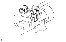
16. CONNECT WIRE HARNESS
(a) Install the wire harness clamp bracket with the bolt.
Torque : 10 Nm (102 kgf-cm, 7 ft-lbf)
(b) Engage the wire harness clamp.
(c) Connect the ground cable with the bolt.
Torque : 13 Nm (133 kgf-cm, 10 ft-lbf)
(d) Connect the 2 connectors.
(e) Connect the 2 connectors.
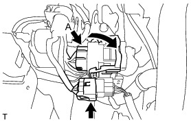
HINT
Press down the lever until the claw of the connector A makes a connection sound.
17. INSTALL STARTER ASSEMBLY
Installation
18. INSTALL FRONT STABILIZER BAR
Installation
19. INSTALL PROPELLER SHAFT WITH CENTER BEARING ASSEMBLY
Installation
20. INSTALL SHIFT LEVER CAP
(a) Install the shift lever cap with the 4 bolts.
Torque : 7.5 Nm (77 kgf-cm, 66 in-lbf)
21. INSTALL SHIFT LEVER BOOT
(a) Install the shift lever boot and shift and select lever retainer with the 4 bolts.
Torque : 18 Nm (184 kgf-cm, 13 ft-lbf)
(b) Connect the wire harness clamp.
(c) Install the shift and select lever cover with the 2 clips.
22. INSTALL CONSOLE BOX ASSEMBLY
Installation
23. CONNECT CABLE TO NEGATIVE BATTERY TERMINAL
24. ADD MANUAL TRANSMISSION OIL Service and Repair
25. INSPECT MANUAL TRANSMISSION OIL Testing and Inspection
26. INSPECT FOR MANUAL TRANSMISSION OIL LEAK
27. INSTALL NO. 2 ENGINE UNDER COVER Installation
28. INSTALL NO. 1 ENGINE UNDER COVER Installation