Rear Window Defogger System Does Not Operate
WINDOW / GLASS: WINDOW DEFOGGER SYSTEM: Rear Window Defogger System does not Operate; 2013 MY FR-S [03/2012 -]
- Rear Window Defogger System does not Operate
DESCRIPTION
When the ignition is ON, operating the rear window defogger switch activates the rear window defogger.
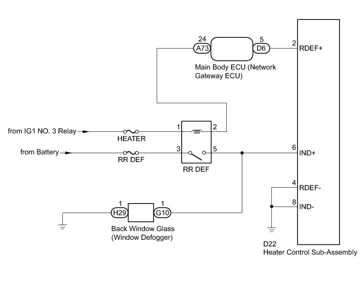
The rear window defogger control is performed by the main body ECU (network gateway computer). When the main body ECU (network gateway computer) receives an on signal from the rear window defogger switch, it operates the RR DEF relay for 15 minutes. Also, when the main body ECU (network gateway computer) receives an off signal from the rear window defogger switch within 15 minutes, it stops operation of the RR DEF relay.
WIRING DIAGRAM
INSPECTION PROCEDURE
NOTICE:
Inspect the fuses for circuits related to this system before performing the following inspection procedure.
PROCEDURE
1. PERFORM ACTIVE TEST USING TECHSTREAM (RR DEF RELAY)
(a) Connect the Techstream to the DLC3.
(b) Turn the ignition switch to ON.
(c) Turn the Techstream on.
(d) Enter the following menus: Body / Main Body / Active Test.
(e) According to the display on the Techstream, perform the Active Test.
Main Body
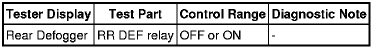
OK:
The window defogger system operates normally.
Result
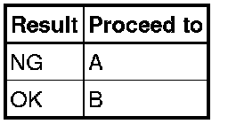
B -- PROCEED TO NEXT CIRCUIT INSPECTION SHOWN IN PROBLEM SYMPTOMS TABLE Problem Symptoms Table
A -- Continue to next step.
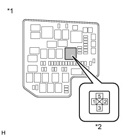
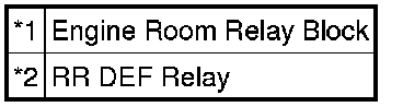
2. INSPECT RR DEF RELAY
(a) Remove the RR DEF relay from the engine room relay block.
(b) Inspect the RR DEF relay Testing and Inspection.
NG -- REPLACE RELAY (RR DEF)
OK -- Continue to next step.
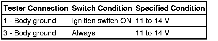
3. CHECK HARNESS AND CONNECTOR (RR DEF RELAY - BATTERY)
(a) Remove the RR DEF relay from the engine room relay block assembly.
(b) Measure the voltage according to the value(s) in the table below.
Standard Voltage:
NG -- REPAIR OR REPLACE HARNESS OR CONNECTOR
OK -- Continue to next step.
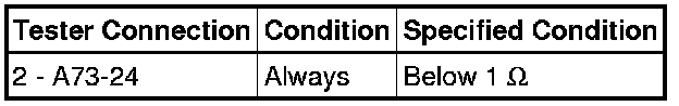
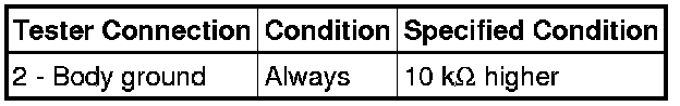
4. CHECK HARNESS AND CONNECTOR (RR DEF RELAY - MAIN BODY ECU (NETWORK GATEWAY ECU))
(a) Remove the RR DEF relay from the engine room relay block assembly.
(b) Disconnect the A73 main body ECU (network gateway ECU) connector.
(c) Measure the resistance according to the value(s) in the table below.
Standard Resistance (Check for Open):
Standard Resistance (Check for Short):
NG -- REPAIR OR REPLACE HARNESS OR CONNECTOR
OK -- Continue to next step.
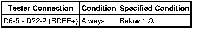
5. CHECK HARNESS AND CONNECTOR (MAIN BODY ECU (NETWORK GATEWAY ECU) - HEATER CONTROL SUB-ASSEMBLY)
(a) Disconnect the D6 main body ECU (network gateway ECU) connector.
(b) Disconnect the D22 heater control sub-assembly connector.
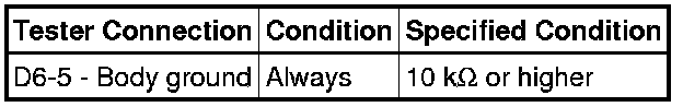
(c) Measure the resistance according to the value(s) in the table below.
Standard Resistance (Check for Open):
Standard Resistance (Check for Short):
NG -- REPAIR OR REPLACE HARNESS OR CONNECTOR
OK -- Continue to next step.
6. INSPECT HEATER CONTROL SUB-ASSEMBLY
(a) Remove the heater control sub-assembly Removal.
(b) Inspect the heater control sub-assembly Testing and Inspection.
NG -- REPLACE HEATER CONTROL SUB-ASSEMBLY Removal
OK -- Continue to next step.
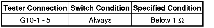
7. CHECK HARNESS AND CONNECTOR (BACK WINDOW GLASS (REAR WINDOW DEFOGGER) - RR DEF RELAY)
(a) Disconnect the G10 and H29 rear window defogger connector.
(b) Remove the RR DEF relay from the engine room relay block assembly.
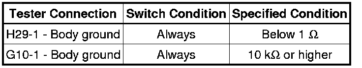
(c) Measure the resistance according to the value(s) in the table below.
Standard Resistance (Check for Open):
Standard Resistance (Check for Short):
NG -- REPAIR OR REPLACE HARNESS OR CONNECTOR
OK -- REPAIR OR REPLACE BACK WINDOW GLASS (REAR WINDOW DEFOGGER) Removal