ECM Power and Ground Supply
DIAGNOSTIC CHARTDiagnostic Chart:
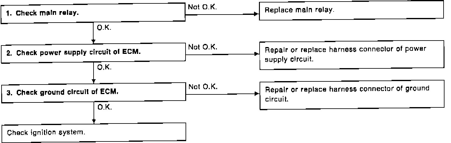
CHECK MAIN RELAY
Main Relay:
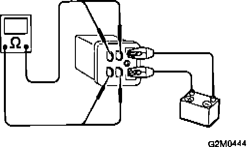
1. Turn ignition OFF.
2. Remove main relay.
3. Connect battery to relay terminals No. 1 and No. 2.
4. Measure resistance between relay terminals.
Terminals Resistance
No. 3 - 5 10 ohms max.
No. 4 - 6 10 ohms max.
CHECK POWER SUPPLY CIRCUIT OF ECM
Voltage Check:
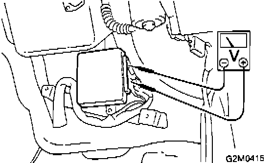
1. Install main relay.
2. Unplug ECM connectors.
3. Turn ignition ON.
4. Measure power supply voltage between ECM connector terminals and body.
Connector & Terminal Voltage
(E29) 13 - body 10 V min.
(E29) 26 - body 10 V min.
CHECK ECM GROUND CIRCUIT
Harness Terminals:
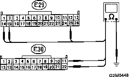
1. Turn ignition OFF.
2. Measure resistance of harness connector between ECM and body.
Connector & Terminal Resistance
(E29) 25 - body 10 ohms max.
(E29) 14 - body 10 ohms max.
(E29) 15 - body 10 ohms max.
(E30) 11 - body 10 ohms max.
(E30) 22 - body 10 ohms max.