Deceleration Mixture Control System
Fig. 17 Deceleration mixture control system schematic:
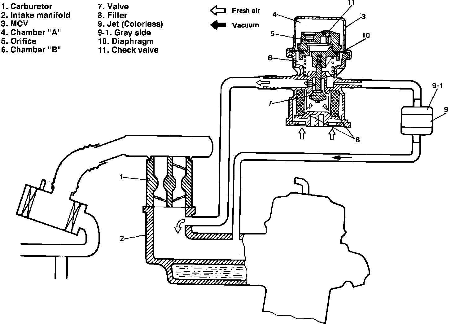
This system, Fig. 17, is designed to allow fresh air into the intake manifold to reduce excessive HC and CO emission caused by temporary rich air fuel ratio during rapid deceleration.
This system consists of a MCV, jet and vacuum hoses. The MCV consists of a pressure balancing orifice and a check valve on its diaphragm, and closes when manifold vacuum is constant.
When manifold vacuum becomes constant, pressure difference between chambers A and B, Fig. 17, gradually diminishes through the pressure balancing orifice, then the MCV.
Fig. 18 Checking mixture control valve operation:
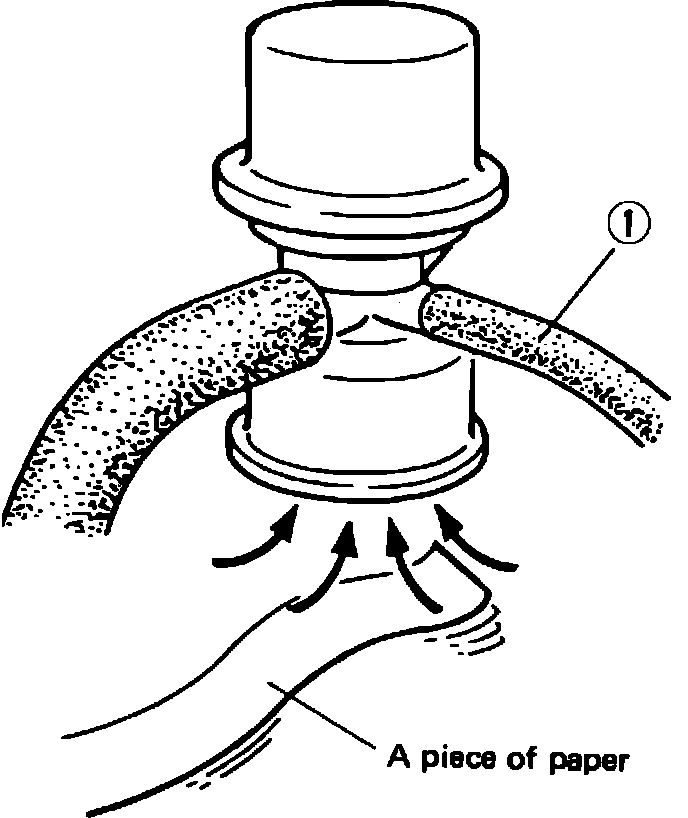
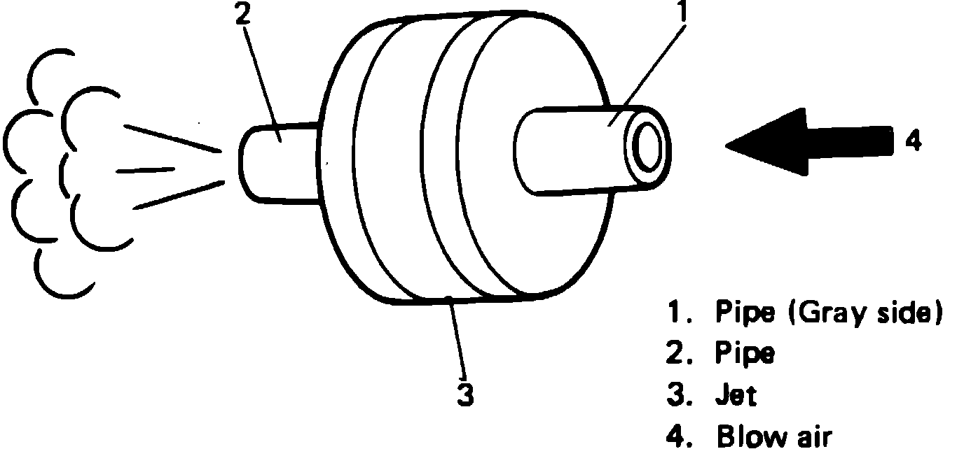
Fig. 19 Checking jet operation:
Testing
DECELERATION MIXTURE
CONTROL SYSTEM
1. Check all hoses for pinholes, cracks or damage. Replace if necessary.
2. Start engine and allow to reach normal operating temperatures.
3. Disconnect hose (1), Fig. 18, then reconnect hose. Ensure air is drawn into MCV. At this time, engine will idle rough or die. This is normal.
4. Remove jet, Fig. 19, then blow air into pipe (1) and ensure air comes out pipe (2). If not, replace jet.