Inspection of Keyless Start Control Module and Its Circuits
Inspection of Keyless Start Control Module and Its CircuitsKeyless start control module and its circuits can be checked at keyless start control module wiring couplers by measuring voltage and resistance.
CAUTION: Keyless start control module cannot be checked by itself. It is strictly prohibited to connect voltmeter or ohmmeter to keyless start control module with coupler disconnected from it.
Voltage Check
1. Disconnect negative cable (-) at battery.
2. Remove keyless start control module from vehicle body referring to Keyless Start Control Module Removal and Installation.
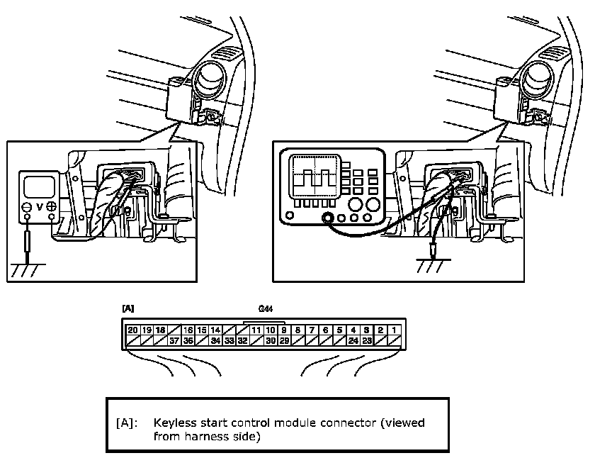
3. Connect connector to keyless start control module.
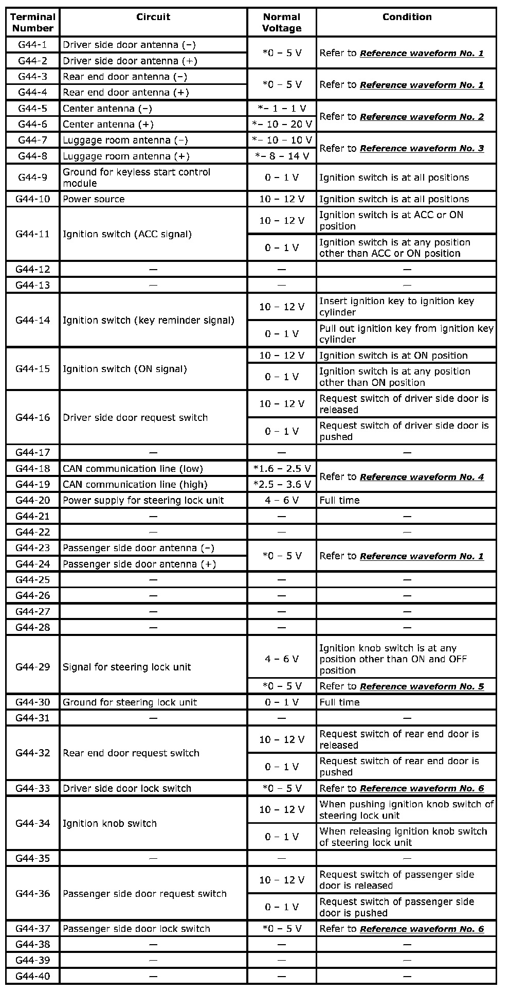
4. Check voltage at each terminal number of couplers connected.
NOTE:
- As each terminal voltage is affected by the battery voltage, confirm that it is 11 V or more when ignition switch is ON.
- Voltage with asterisk (*) cannot be measured by voltmeter because it is pulse signal.
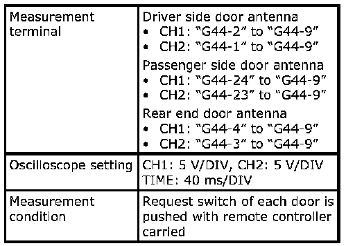
G44-1-G44-40:
Reference wave form No. 1
Driver, passenger and rear end door antenna request signals (Request signal (1) transmitted by each door antenna when each door request switch is pushed)
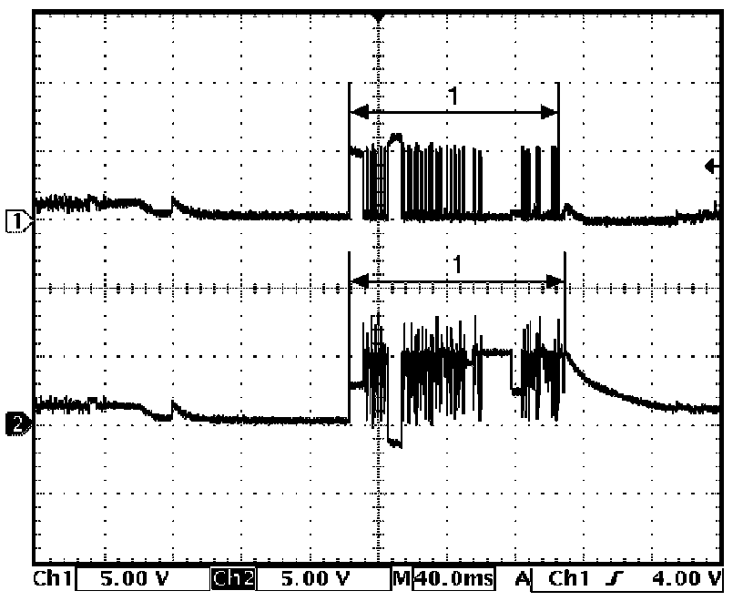
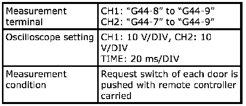
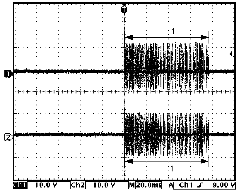
Reference Waveform No. 1:
Reference wave form No. 2
Center antenna signal
(Request signal (1) transmitted by center antenna when each door request switch is pushed)
Reference Waveform No. 2:
Reference wave form No. 3
Luggage room antenna signal
(Request signal (1) transmitted by luggage room antenna when each door request switch is pushed)
Reference Waveform No. 3:
Reference wave form No. 4
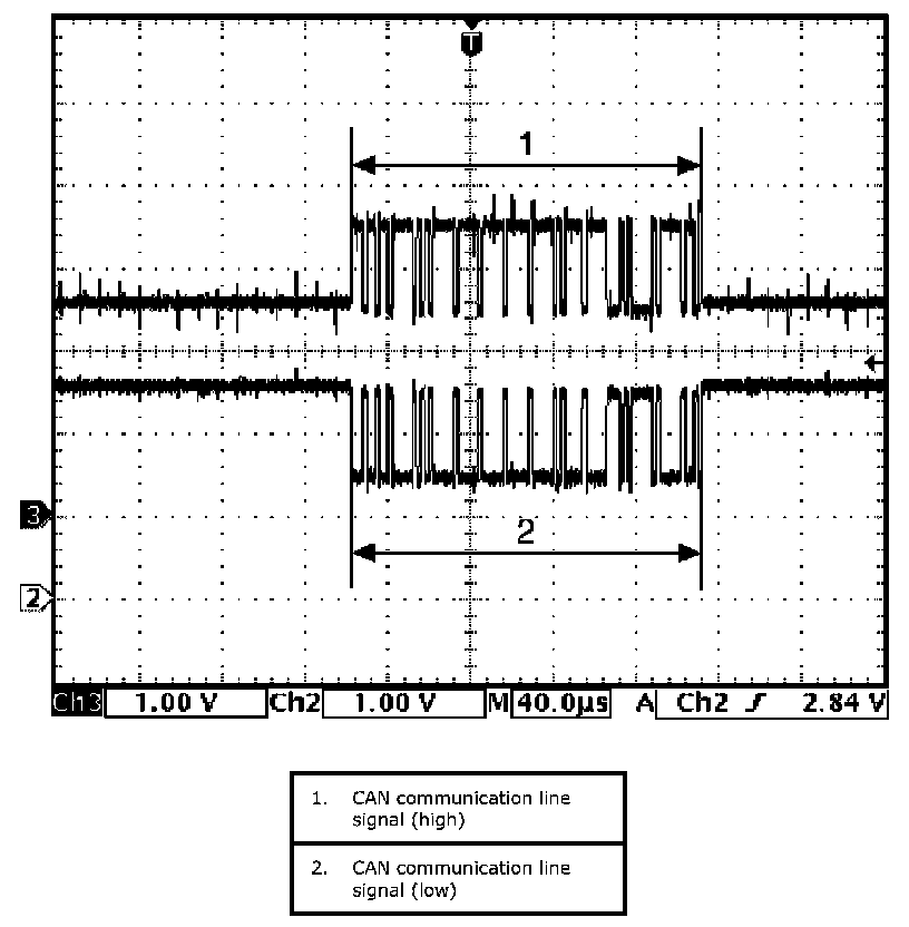
CAN communication signals
(CAN signal communicated to each control module when ignition switch is turned ON)
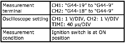
Reference Waveform No. 4:
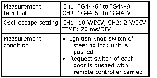
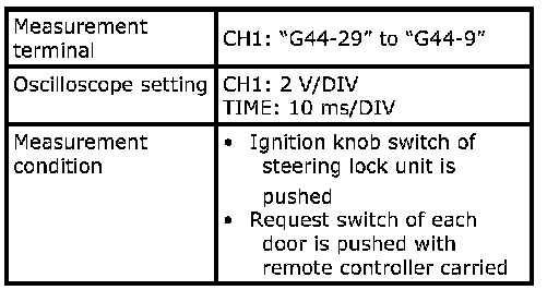
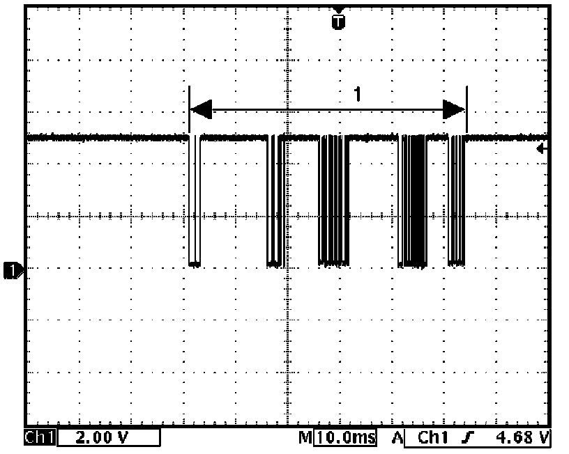
Reference wave form No. 5
Steering lock unit signal
(Signal (1) communicated between keyless start control module and steering lock unit when measurement condition described below applies)
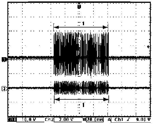
Reference Waveform No. 5:
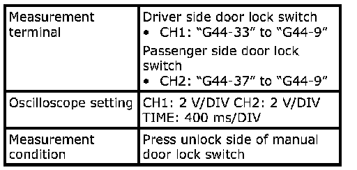
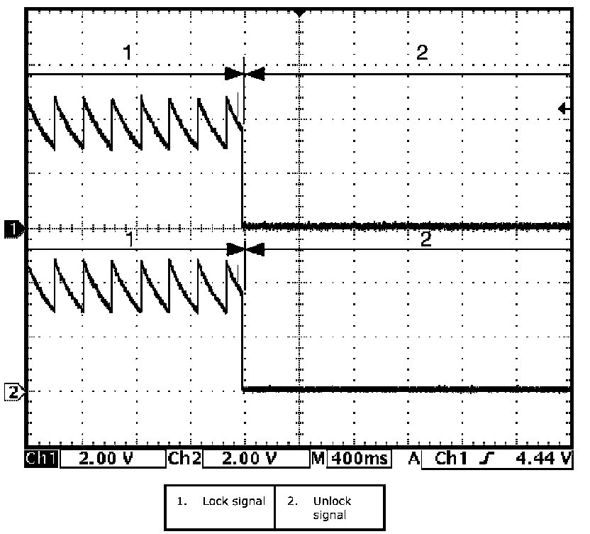
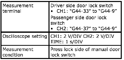
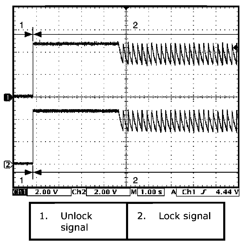
Reference wave form No. 6
Driver and passenger side door lock switch signals.
(This signal indicates door lock status.)
In case the position of driver and passenger side door lock is changed from the unlock to the lock.
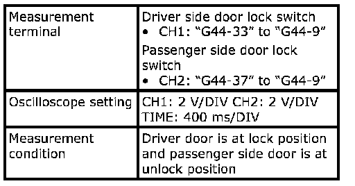
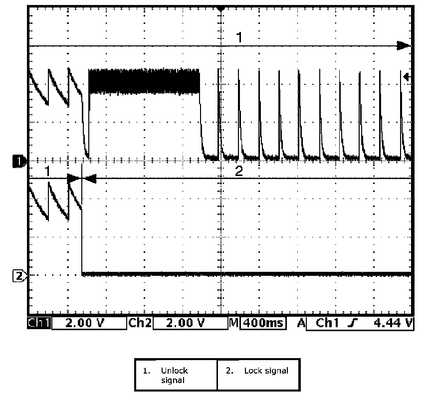
Reference Waveform No. 6:
In case the position of passenger side door lock is changed from the lock to the unlock when the position of driver and passenger side door is at the lock
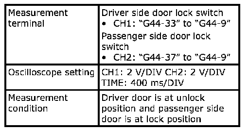
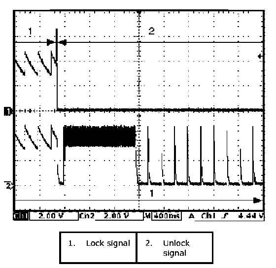
Reference Waveform No. 6:
In case the position of driver side door lock is changed from the lock to the unlock when the position of driver and passenger side door is at the lock.
Reference Waveform No. 6:
In case the position of driver and passenger side door lock is changed from the lock to the unlock.
Reference Waveform No. 6: