Intake Manifold: Removal and Installation
Intake Manifold: Removal and InstallationCAUTION:
Do not remove or disassemble parts unless instructed as shown.
REMOVAL
1) Release fuel pressure.
2) Remove air cleaner case, air cleaner filter and air duct and resonator assembly.
3) Disconnect water hoses from electric throttle control actuator, and pinch water hoses near electric throttle control actuator to prevent engine coolant spilling.
CAUTION:
^ Perform this step when engine is cold.
^ Do not spill engine coolant on drive belt.
4) Remove mass air flow sensor from intake manifold.
CAUTION:
Handle the mass air flow sensor with care:
^ Do not shock it.
^ Do not disassemble it.
^ Do not touch the internal sensor.
5) Remove quick connector cap, and disconnect quick connector at the engine side.
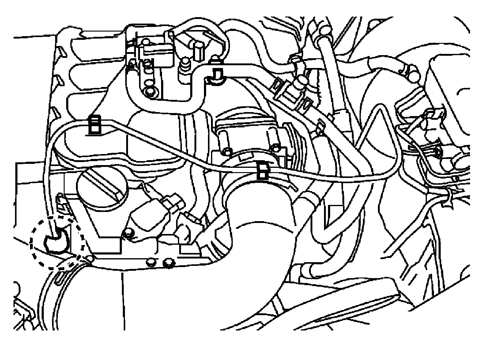
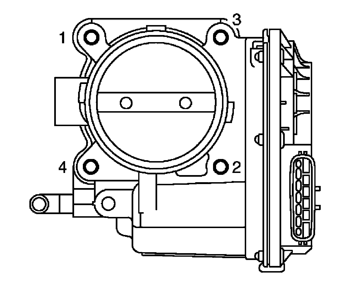
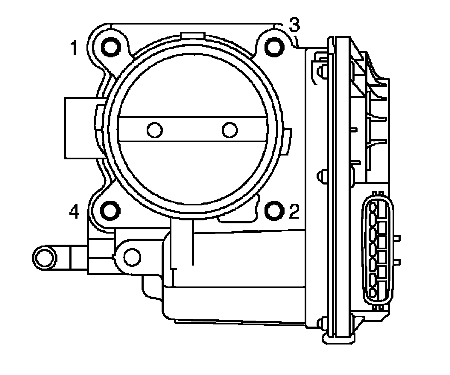
6) Remove electric throttle control actuator as follows:
a) Disconnect harness connector.
b) Loosen bolts in reverse order as shown, and remove electric throttle control actuator and gasket.
CAUTION:
^ Handle carefully to avoid any shock to electric throttle control actuator.
^ Do not disassemble.
7) Disconnect harness, vacuum hoses and PCV hoses from intake manifold, and move them aside.
8) Remove intake manifold support.
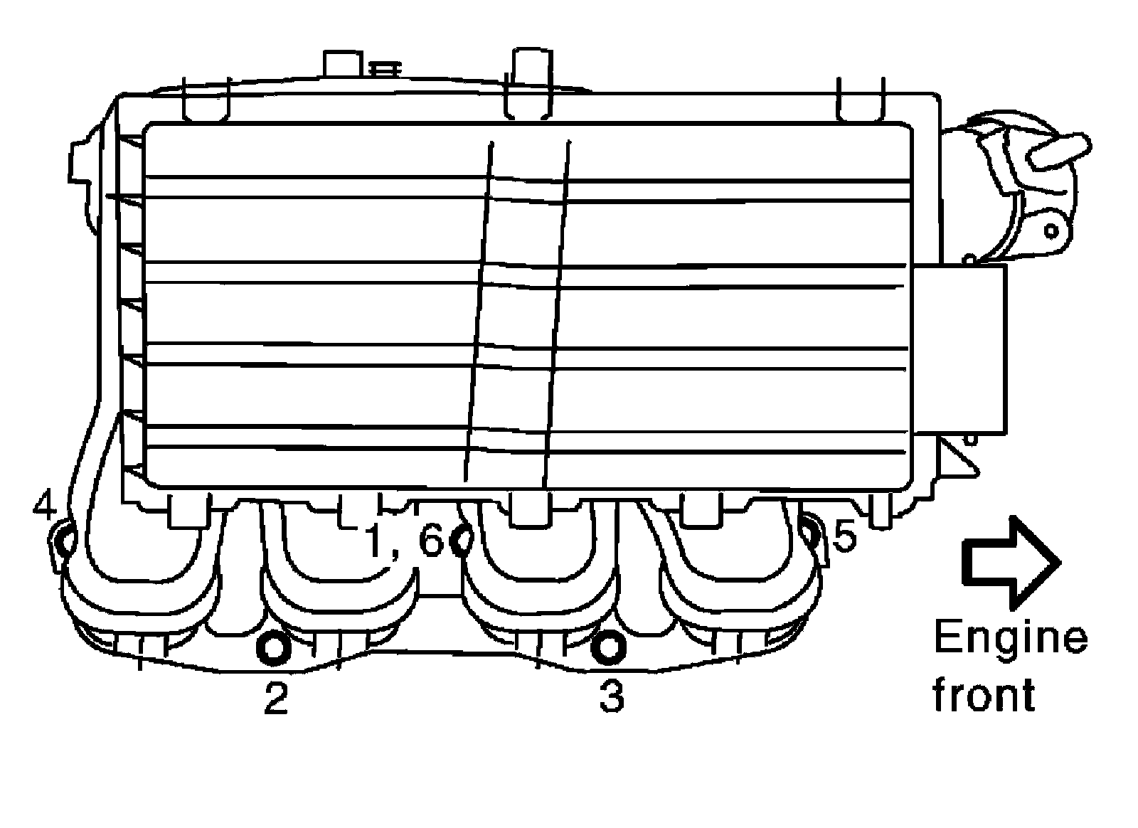
9) Loosen nuts and bolts in reverse order as shown, and remove intake manifold, fuel tube protector and gasket.
CAUTION:
^ Cover engine openings to avoid entry of foreign materials.
^ Do not disassemble intake manifold.
NOTE:
Disregard No. 6 when loosening.
10) Remove EVAP canister purge volume control solenoid valve and vacuum hose adapter from intake manifold, if necessary.
11) Disconnect sub-harness from fuel injector.
12) Remove fuel tube and fuel injector assembly from intake manifold.
INSTALLATION
Installation in the reverse order of removal.
Intake Manifold and Fuel Tube Protector
^ If stud bolts were removed, install them and tighten to the specified torque below.
Intake manifold bolts: 9.4 Nm (0.96 kg-m, 83 in-lb)
^ Tighten in numerical order as shown.
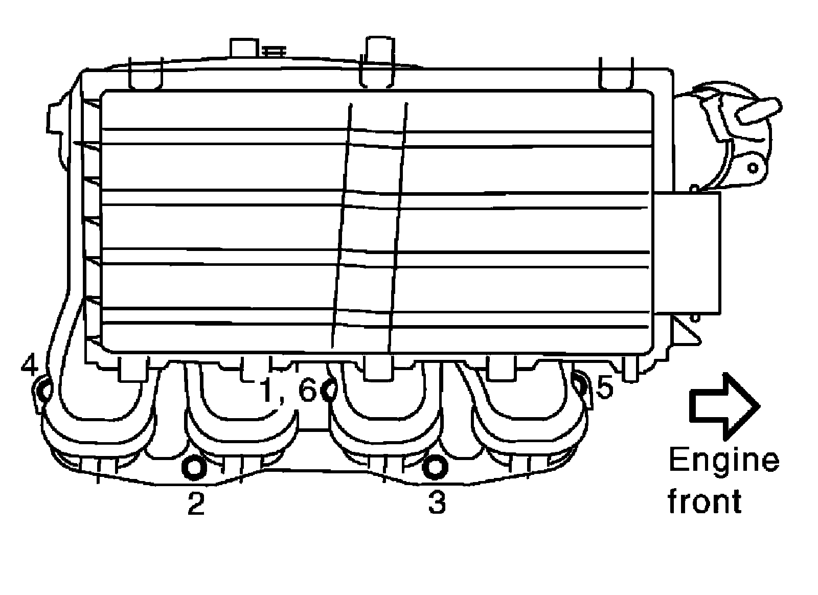
NOTE:
No. 6 means double tightening of bolt No. 1.
Use the following for locating bolts and nuts.
M8 x 38 mm (1.50 in) (Color green): No. 1, 6
M8 x 35 mm (1.38 in): No. 2, 3
Nut: No. 4, 5
Electric Throttle Control Actuator
^ Tighten bolts equally and diagonally in several steps and in numerical order as shown.
^ Perform the "Throttle Valve Closed Position Learning" when harness connector of electric throttle control actuator is disconnected.
^ Perform the "Idle Air Volume Learning" and "Throttle Valve Closed Position Learning" when electric throttle control actuator is replaced.
INSPECTION AFTER INSTALLATION
Make sure there are no fuel leaks at connections as follows:
1) Apply fuel pressure to fuel lines by turning ignition switch ON (with the engine stopped). Then make sure there are no fuel leaks at connections.
2) Start the engine. With engine speed increased, make sure again there are no fuel leaks at connections.
WARNING:
Do not touch the engine immediately after stopped as the engine becomes extremely hot.
NOTE:
Use mirrors for checking on invisible points.