Timing Chain: Removal and Installation
Timing Chain: Removal and InstallationREMOVAL
1) Release the fuel pressure.
2) Remove the air cleaner and air duct assembly.
3) Remove the spark plugs.
4) Remove the rocker cover.
5) Remove the coolant overflow reservoir tank.
6) Remove the drive belt auto-tensioner.
7) Remove the generator.
8) Remove the strut tower brace.
9) Dismount and position aside the A/C compressor with the piping attached.
10) Dismount and position aside the power steering pump and reservoir tank with the piping attached.
11) Remove the oil pan, and oil strainer.
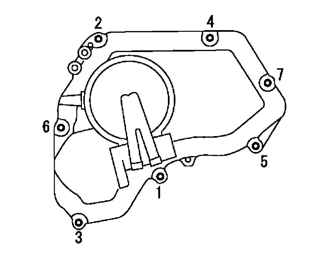
12) Remove IVT control cover bolts in the order as shown.
13) Remove the IVT control cover by cutting the sealant using Tool.
Tool number: KV10111100 (J-37228)
14) Pull chain guide between camshaft sprockets out through front cover.
15) Set the No. 1 cylinder at TDC on the compression stroke with the following procedure:
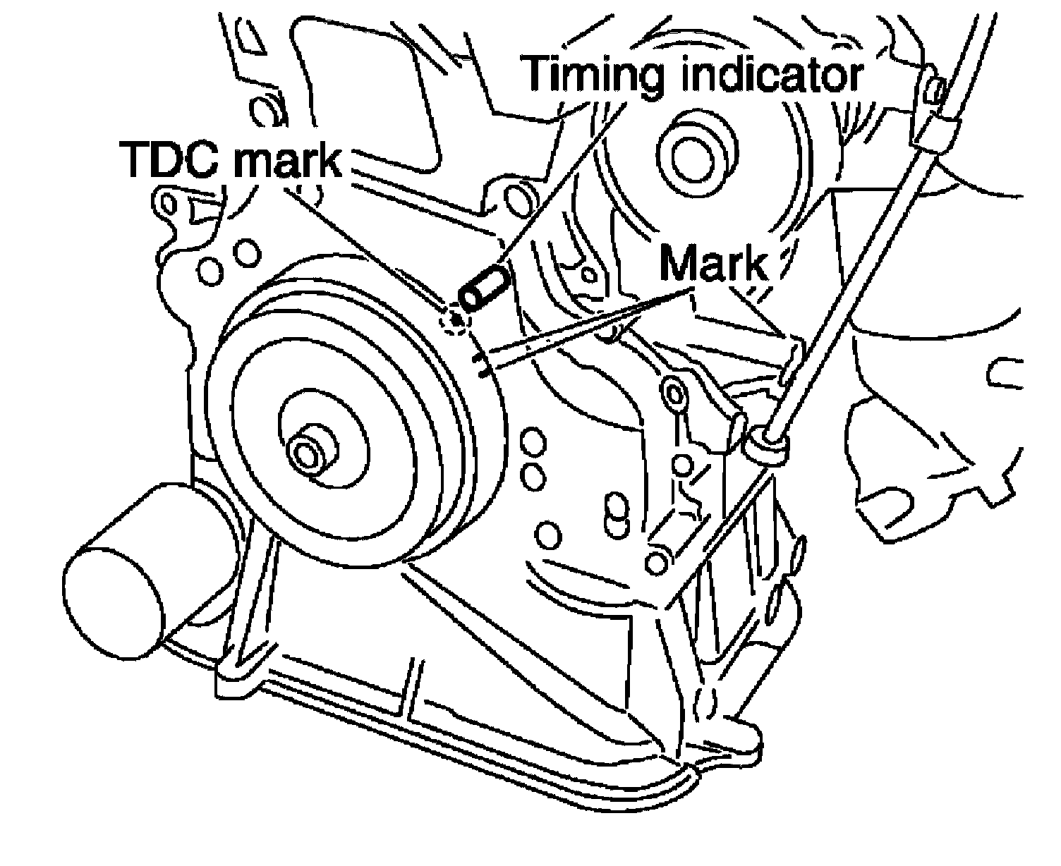
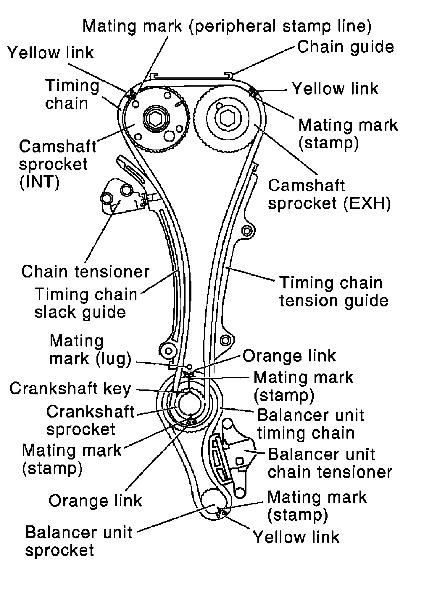
a) Rotate the crankshaft pulley clockwise and align the mating marks to the timing indicator on the front cover.
b) At the same time, make sure that the mating marks on the camshaft sprockets are lined up as shown.
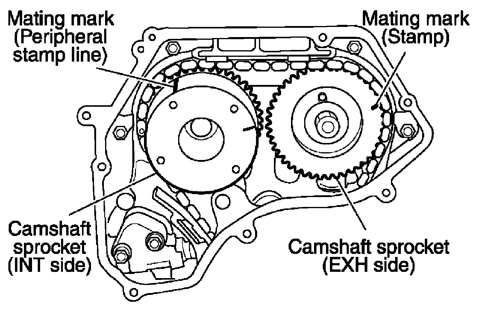
^ If not lined up, rotate the crankshaft pulley one more turn to line up the mating marks to the positions as shown.
1) Remove crankshaft pulley with the following procedure:
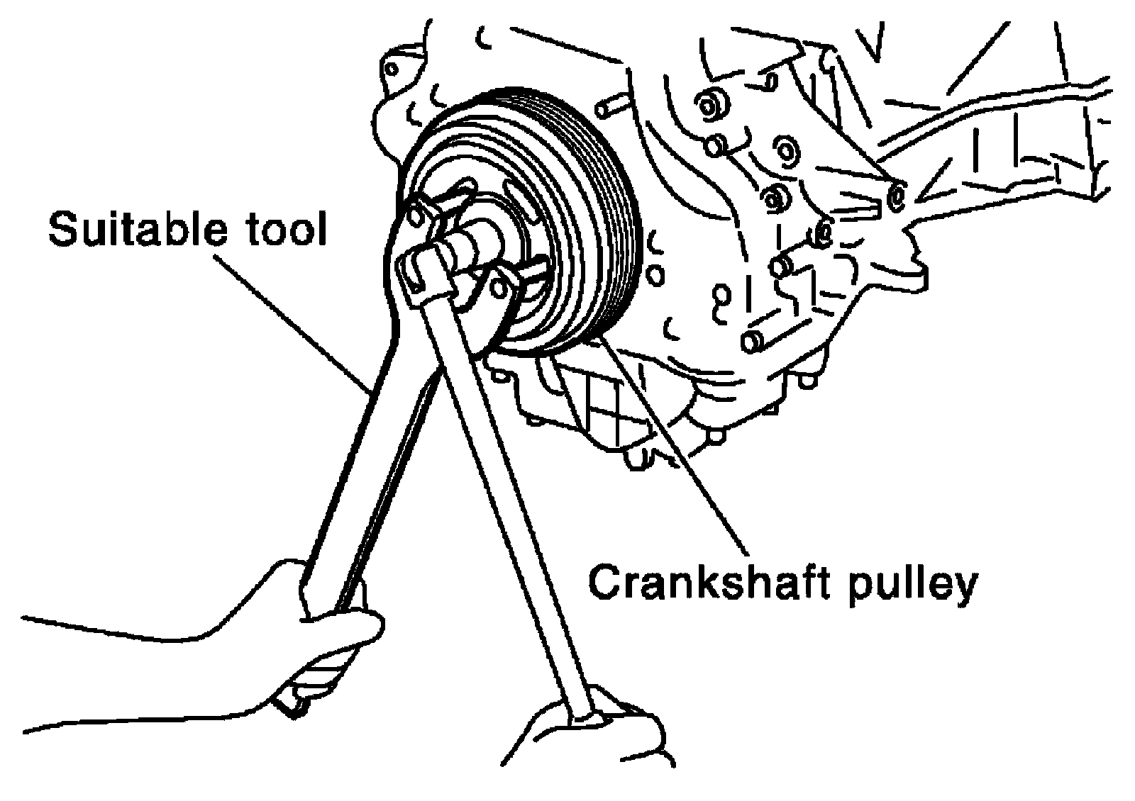
a) Hold the crankshaft pulley with a suitable tool, then loosen the crankshaft pulley bolt, and pull the pulley out about 10 mm (0.39 in). Remove the crankshaft pulley bolt.
b) Attach a pulley puller in the M6 (0.24 in diameter) thread hole on crankshaft pulley, and remove crankshaft pulley.
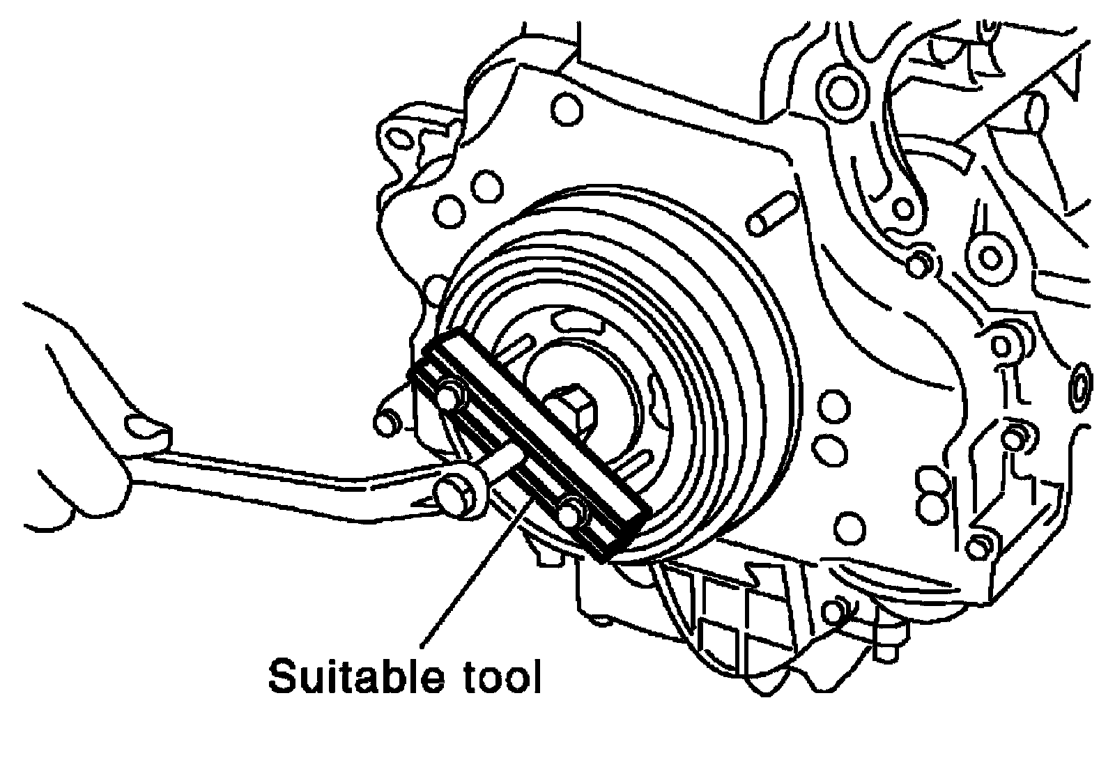
2) If the front oil seal needs to be replaced, remove it using a suitable tool.
3) Remove the front cover as follows:
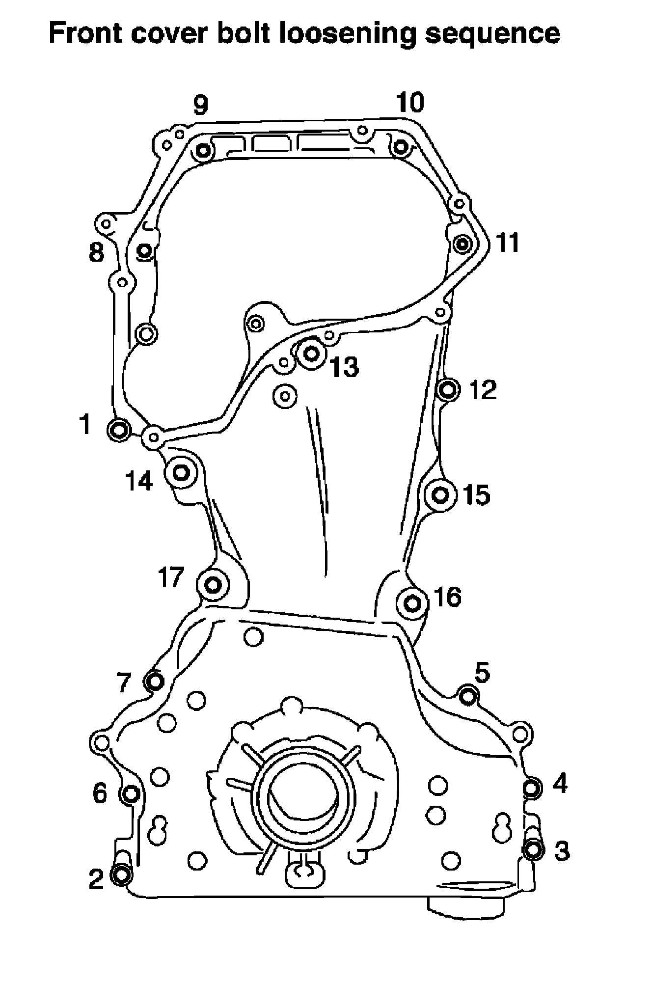
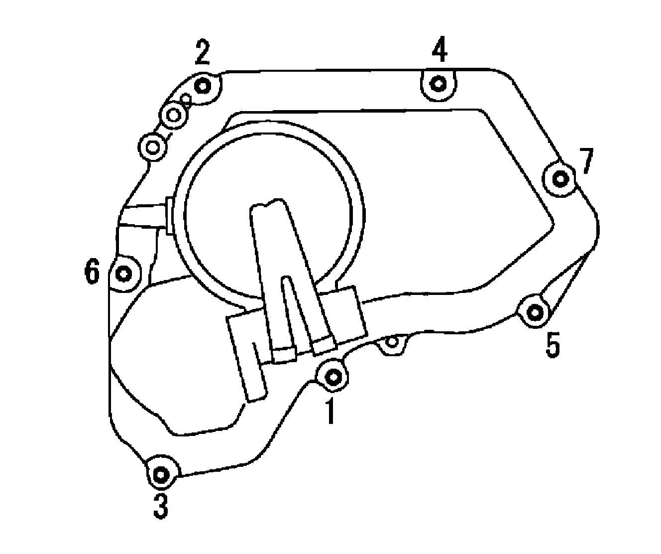
a) Loosen the front cover bolts in the order as shown, and remove them.
b) Remove the front cover.
CAUTION:
^ Be careful not to damage the mating surface.
4) Remove timing chain with the following procedure:
a) Push in chain tensioner plunger. Insert a stopper pin into hole on chain tensioner body to secure chain tensioner plunger and remove chain tensioner.
NOTE:
Use approximately 0.5 mm (0.02 in) dia. hard metal pin as a stopper pin.
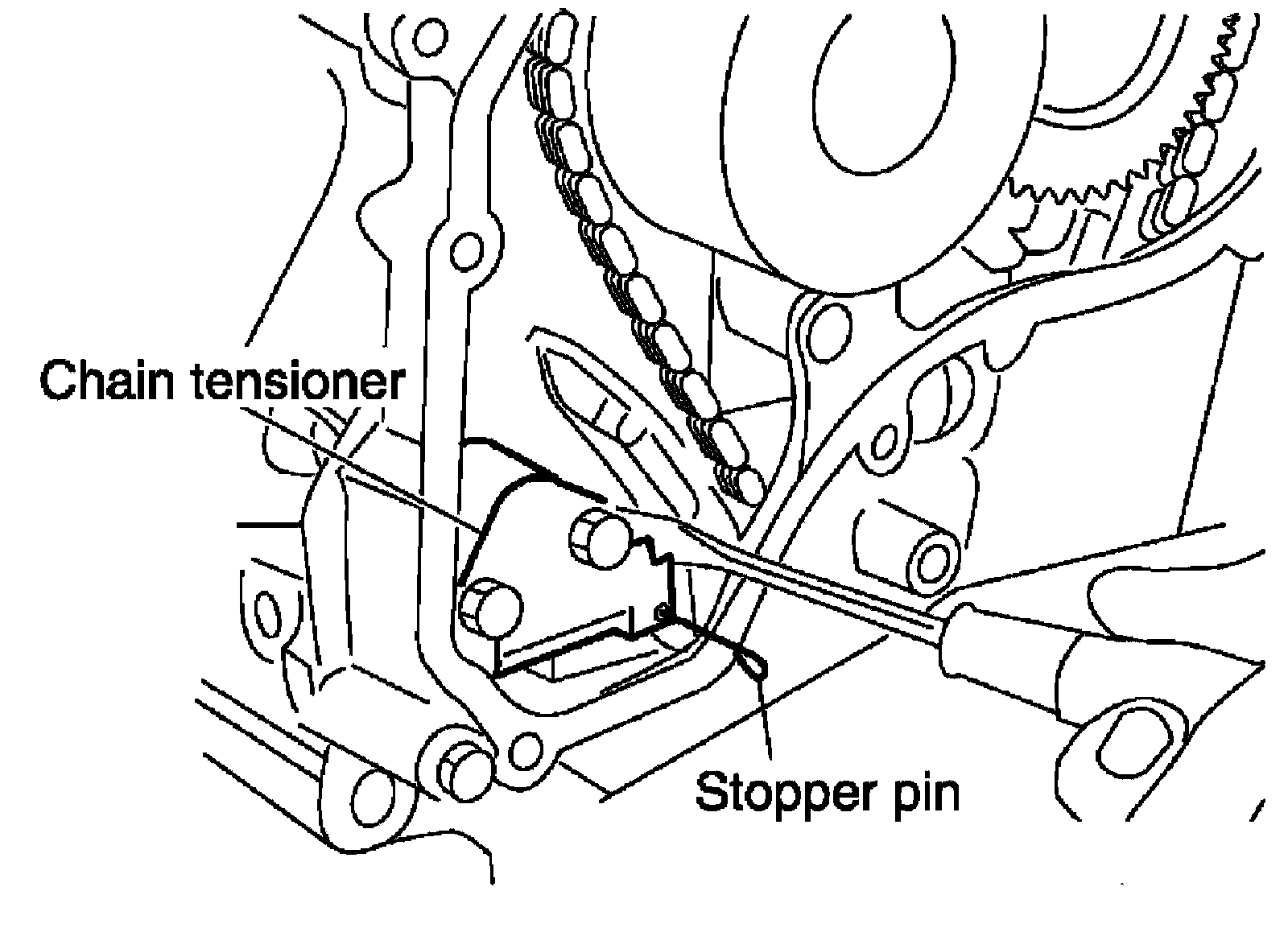
b) Remove timing chain.
CAUTION:
Do not rotate crankshaft or camshaft while timing chain is removed. It causes interference between valve and piston.
5) Remove camshaft sprockets.
6) Remove timing chain slack guide, timing chain tension guide and spacer.
7) Remove balancer unit timing chain tensioner with the following procedure:
a) Lift lever up, and release ratchet claw for return proof.
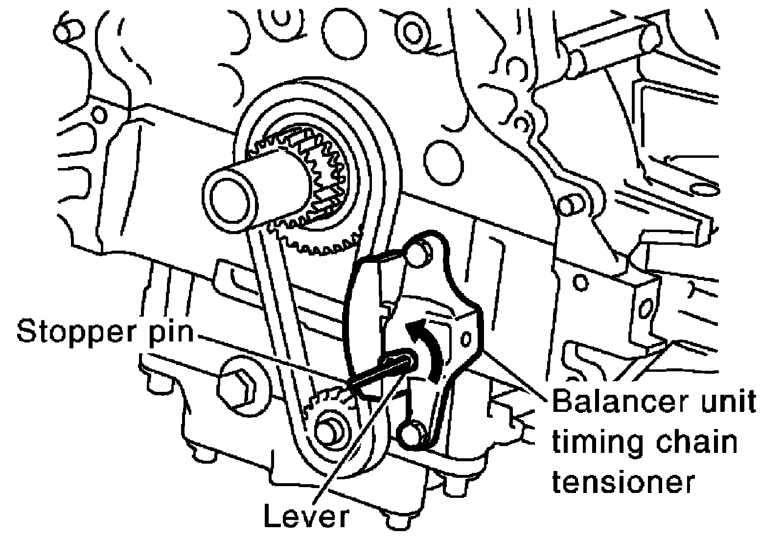
b) Push tensioner sleeve in, and hold it.
c) Matching the hole on lever with the one on body, insert a stopper pin to secure tensioner sleeve.
NOTE:
Use approximately 1 mm (0.04 in) dia. hard metal pin as a stopper pin.
d) Remove balancer unit timing chain tensioner.
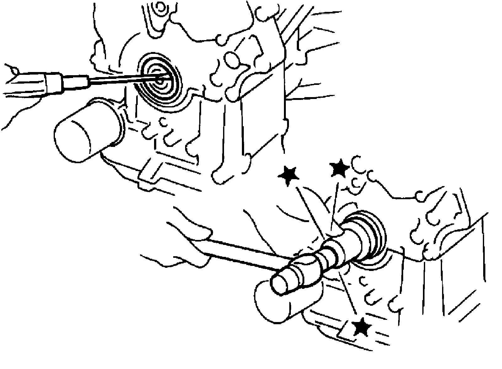
8) Secure the hexagonal portion of the balancer shaft using a suitable tool. Loosen the balancer unit sprocket bolt.
9) Remove balancer unit timing chain, balancer unit sprocket and crankshaft sprocket.
NOTE:
When removing balancer unit timing chain, remove crankshaft sprocket and balancer unit sprocket at the same time.
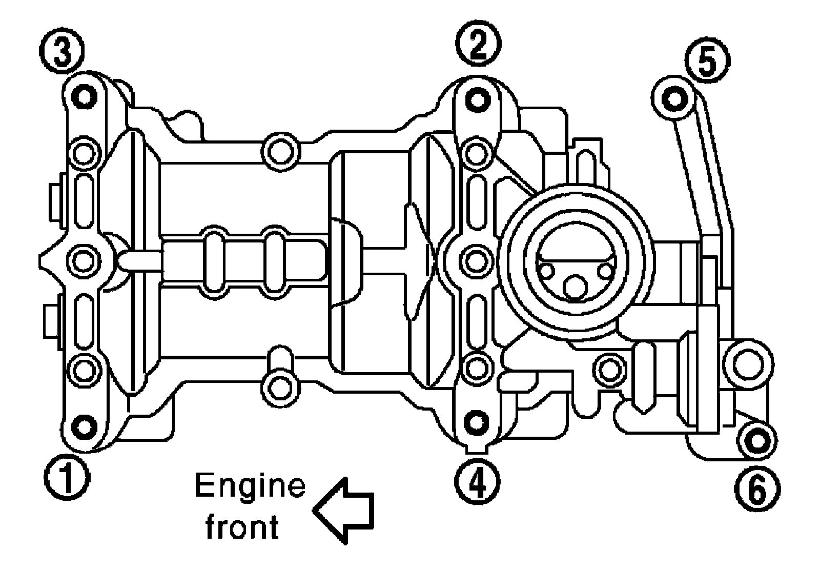
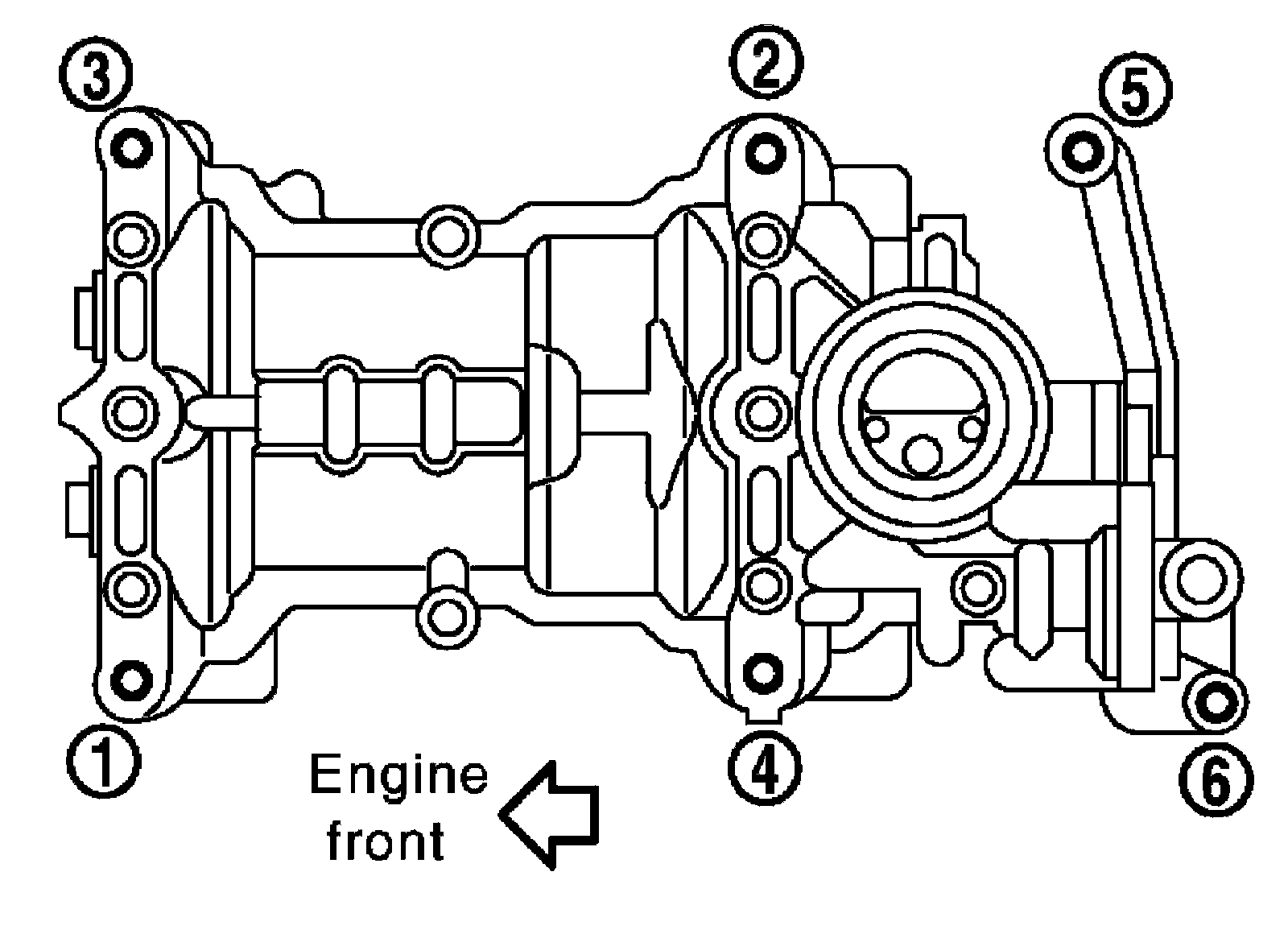
1) Loosen bolts in reverse order as shown, and remove balancer unit.
CAUTION:
Do not disassemble balancer unit.
NOTE:
Use TORX socket (size E14) for bolts No.1 to 4.
INSPECTION AFTER REMOVAL
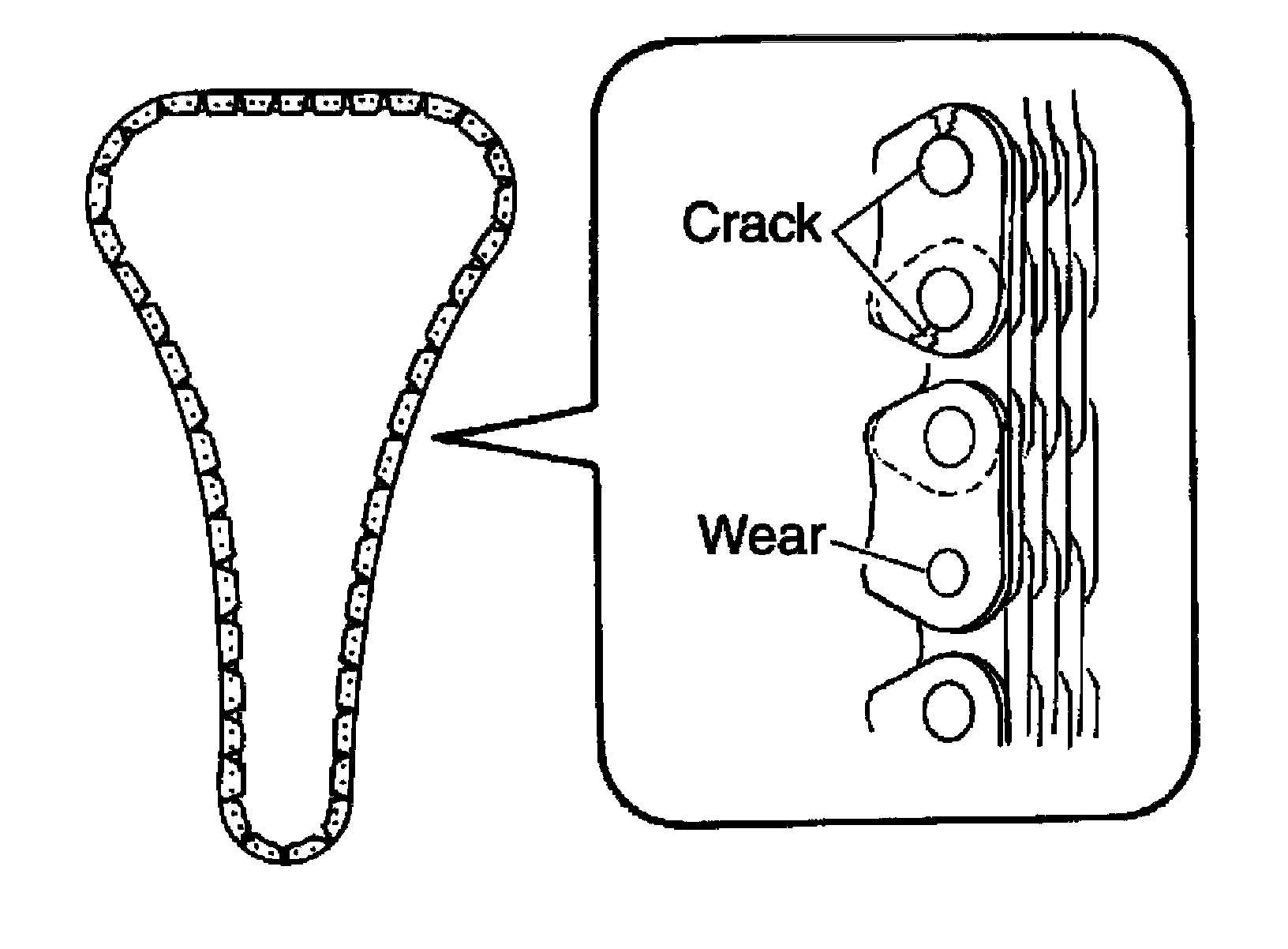
Timing Chain
Check timing chain for cracks and any excessive wear at the roller links of timing chain. Replace timing chain if necessary.
Balancer Unit Bolt Outer Diameter
^ Measure outer diameters [(d1), (d2)] at two positions as shown.
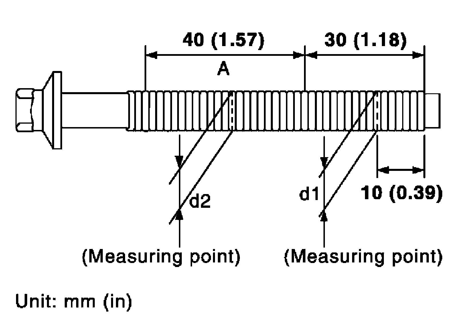
^ If reduction appears in (A) range, regard it as (d2).
Limit [(d1), - (d2)]: 0.15 mm (0.0059 in)
^ If it exceeds the limit (large difference in dimensions), replace balancer unit bolt with a new one.
Balancer Unit Bolt Length
Measure balancer unit bolt length. If it exceeds the limit, replace balancer unit bolt with a new one.
Limit: 172 mm (6.77 in)
INSTALLATION
NOTE:
The figure shows the relationship between the mating mark on each timing chain and that on the corresponding sprocket, with the components installed.
1) Make sure that crankshaft key points straight up.
2) Install O-ring to balancer unit.
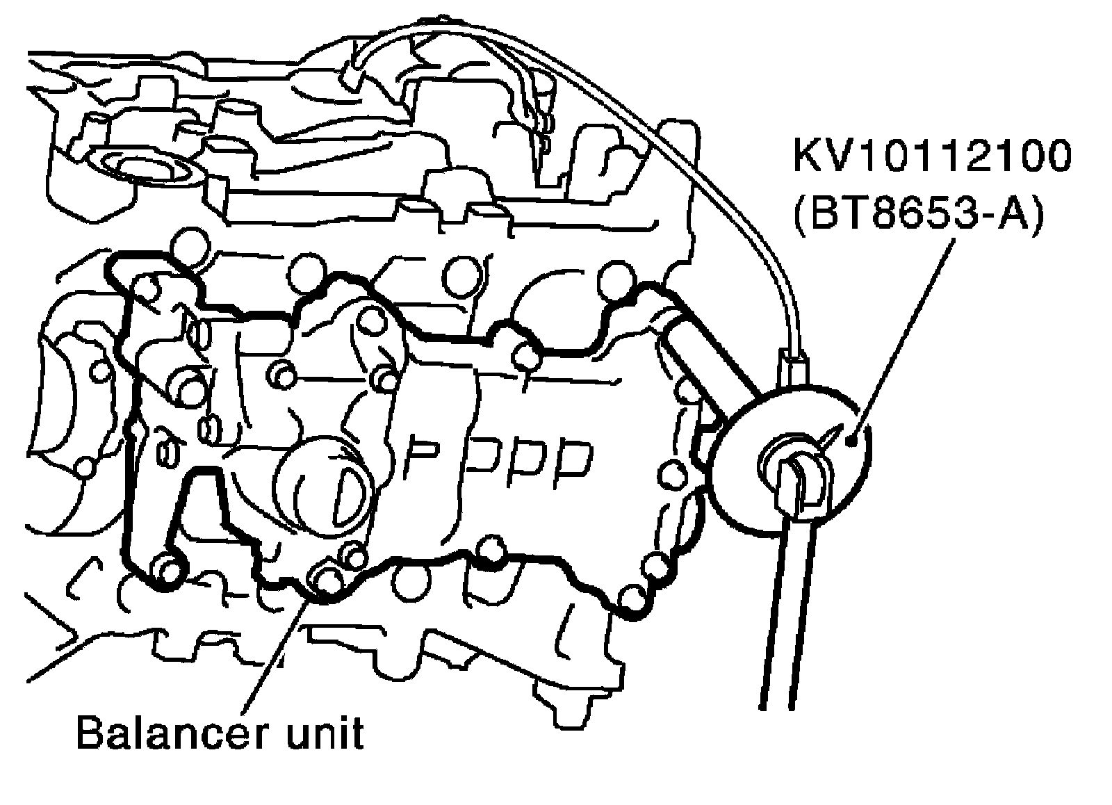
3) Tighten bolts in numerical order as shown with the following procedure to install balancer unit, using Tool.
Tool number: KV10112100 (BT8653-A)
CAUTION:
If bolts are re-used, check their outer diameter before installation. Follow the "Balancer Unit Bolt Outer Diameter" procedure.
CAUTION:
^ Check tightening angle using Tool or a protractor. Do not make judgment by visual check alone.
^ In step 3, loosen bolts in reverse order as shown.
NOTE:
Apply new engine oil to threads and seat surfaces of bolts.
Balancer bolt torque
Step 1 bolts 1 - 4: 48.1 Nm (4.9 kg-m, 35 ft-lb)
Step 2 bolts 1 - 4: 100° clockwise
Step 3 bolts 1 - 4: 0 Nm (0 kg-m, 0 ft-lb)
Step 4 bolts 1 - 4: 48.1 Nm (4.9 kg-m, 35 ft-lb)
Step 5 bolts 1 - 4: 100° clockwise
Step 6 bolts 5 - 6: 30.1 Nm (3.1 kg-m, 22 ft-lb)
4) Install crankshaft sprocket, balancer unit sprocket and balancer unit timing chain.
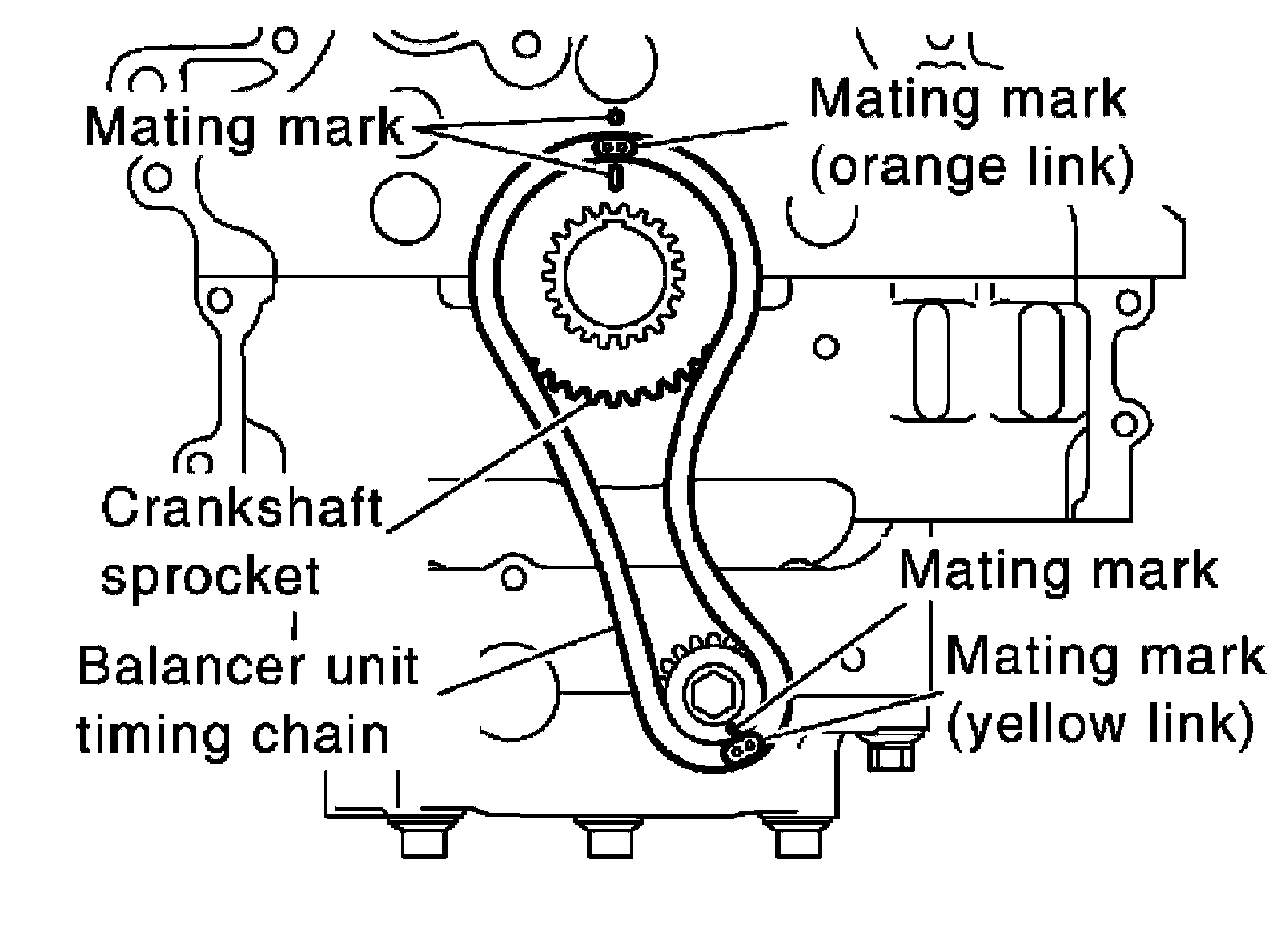
^ Make sure that crankshaft sprocket is positioned with mating marks on cylinder block and crankshaft sprocket meeting at the top.
^ Install it by aligning mating marks on each sprocket and balancer unit timing chain.
^ Secure the hexagonal portion of the balancer shaft using a suitable tool. Tighten the balancer unit sprocket bolt to the specified torque.
NOTE:
Install crankshaft sprocket, balancer unit sprocket and balancer unit timing chain at the same time.
5) Install balancer unit timing chain tensioner.
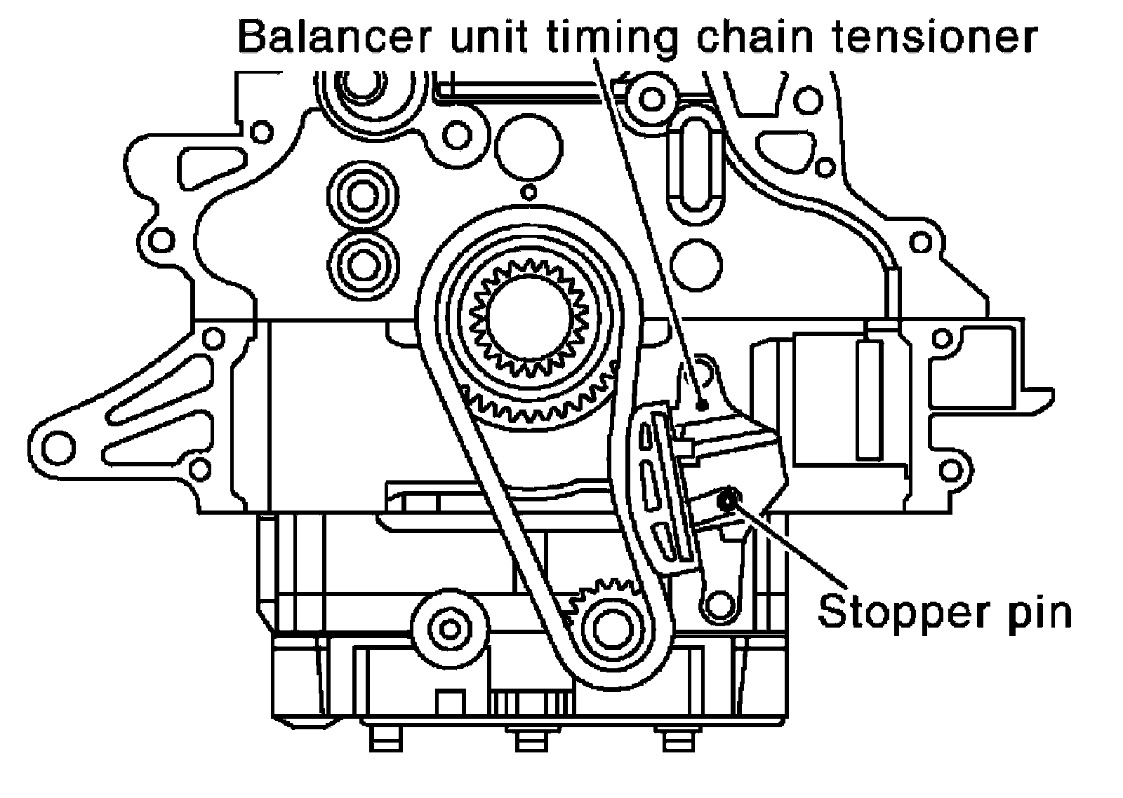
^ After installation, make sure the mating marks have not slipped, then remove stopper pin and release tensioner sleeve.
6) Install timing chain and related parts.
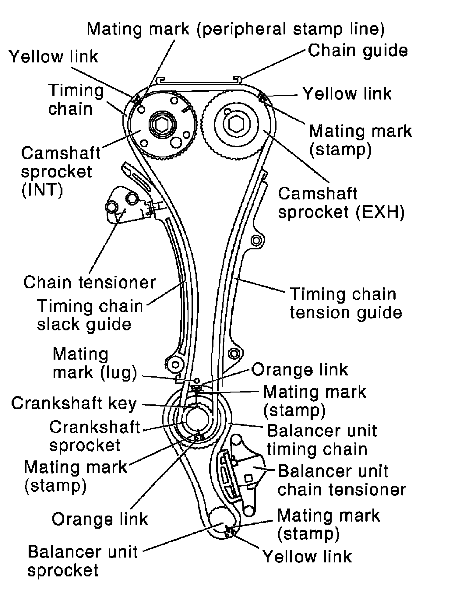
^ Install by aligning mating marks on each sprocket and timing chain.
^ Before and after installing chain tensioner, check again to make sure that mating marks have not slipped.
^ After installing chain tensioner, remove stopper pin, and make sure that tensioner moves freely.
CAUTION:
^ For the following note, after the mating marks are aligned, keep them aligned by holding them with a hand.
^ To avoid skipped teeth, do not rotate crankshaft and camshaft until front cover is installed.
NOTE:
Before installing chain tensioner, it is possible to change the position of mating mark on timing chain for that on each sprocket for alignment.
7) Install front oil seal to front cover.
8) Install O-rings to cylinder head and cylinder block.
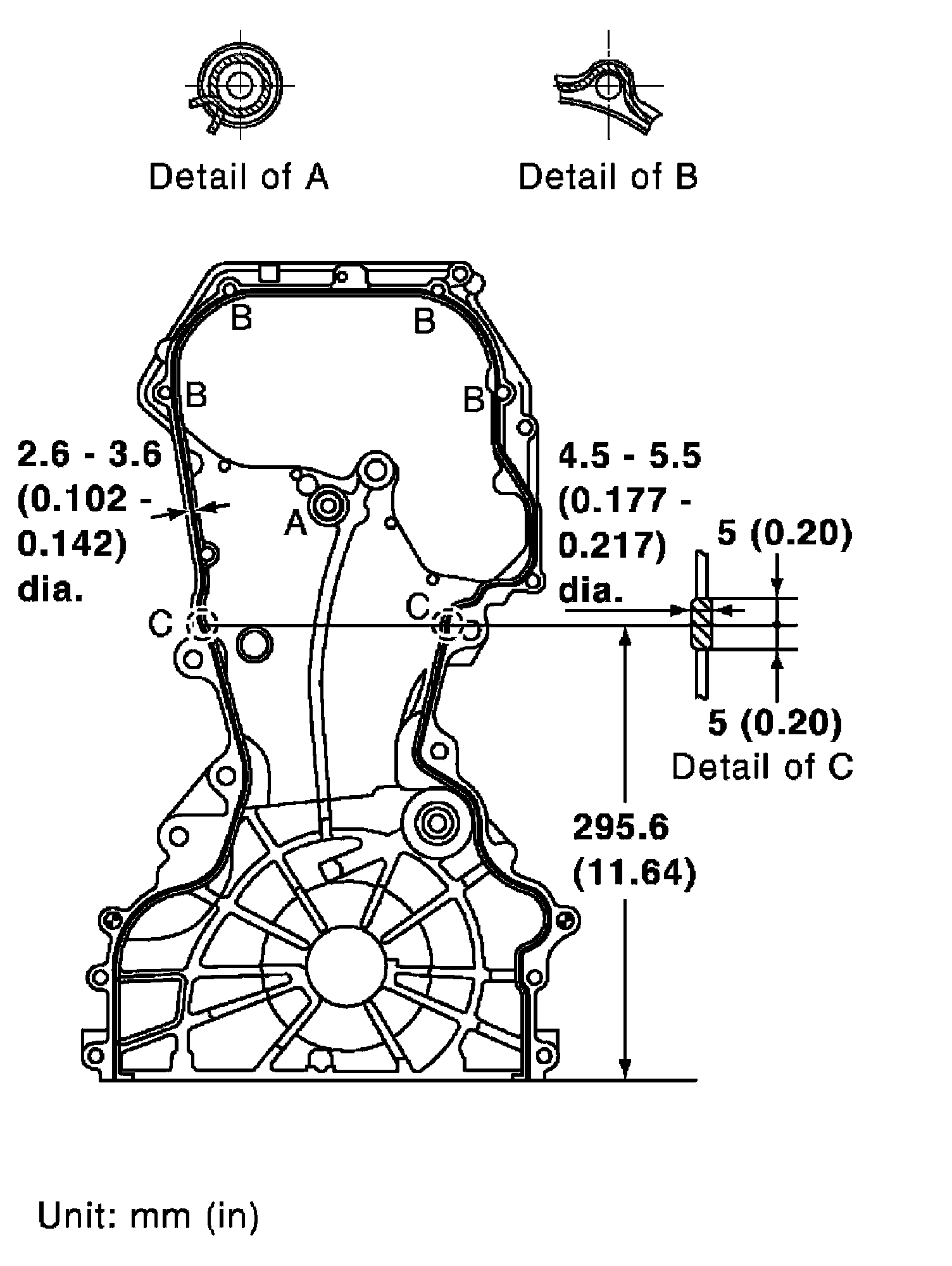
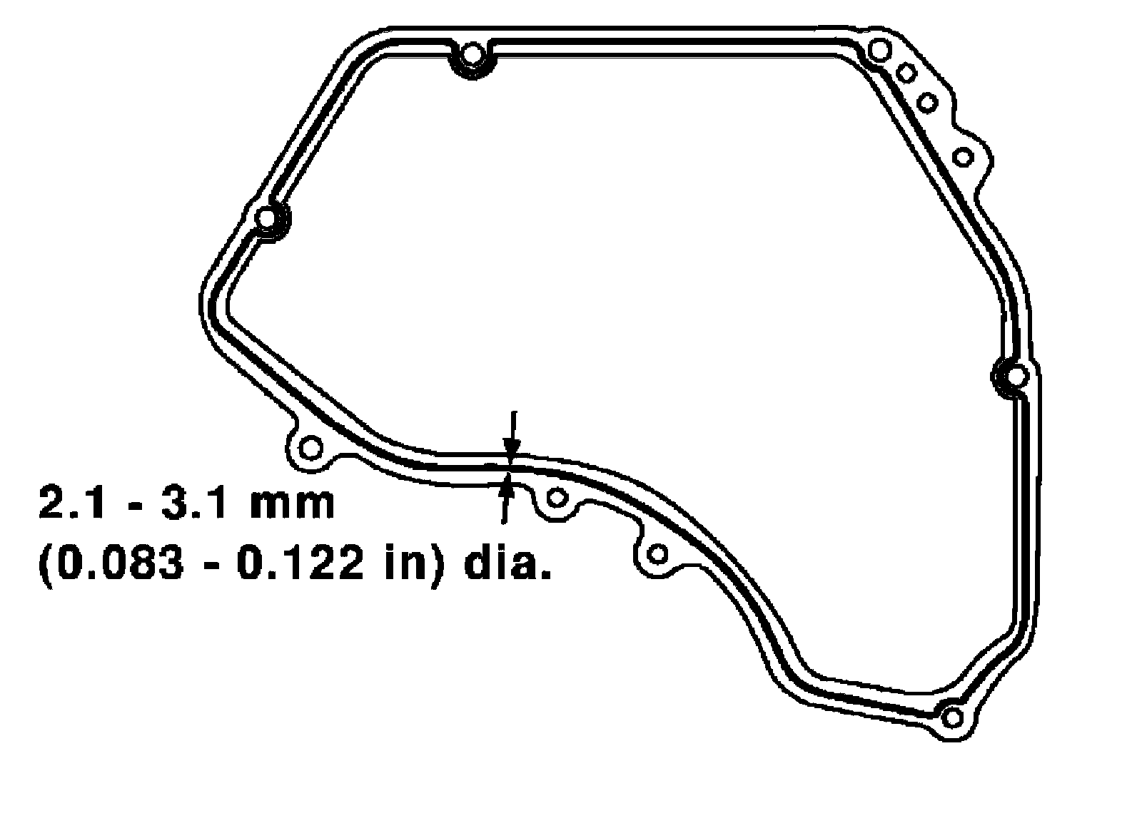
9) Apply a continuous bead of liquid gasket with the tube presser to front cover as shown, using Tool.
Tool number: WS39930000 ( - )
Use Genuine RTV Silicone Sealant or equivalent.
NOTE:
Application instruction differs depending on the position.
Detail of A: Cross over the start of the application and the end.
Detail of B: Apply liquid gasket outside of bolt holes. (For all bolt holes other than B, apply to the inside.)
Detail of C: Between here only, apply 4.5 - 5.5 mm (0.177 - 0.217 in) dia.
10) Make sure that mating marks of timing chain and each sprocket are still aligned. Then install front cover.
CAUTION:
Be careful not to damage front oil seal by interference with front end of crankshaft.
11) Tighten bolts in numerical order as shown.
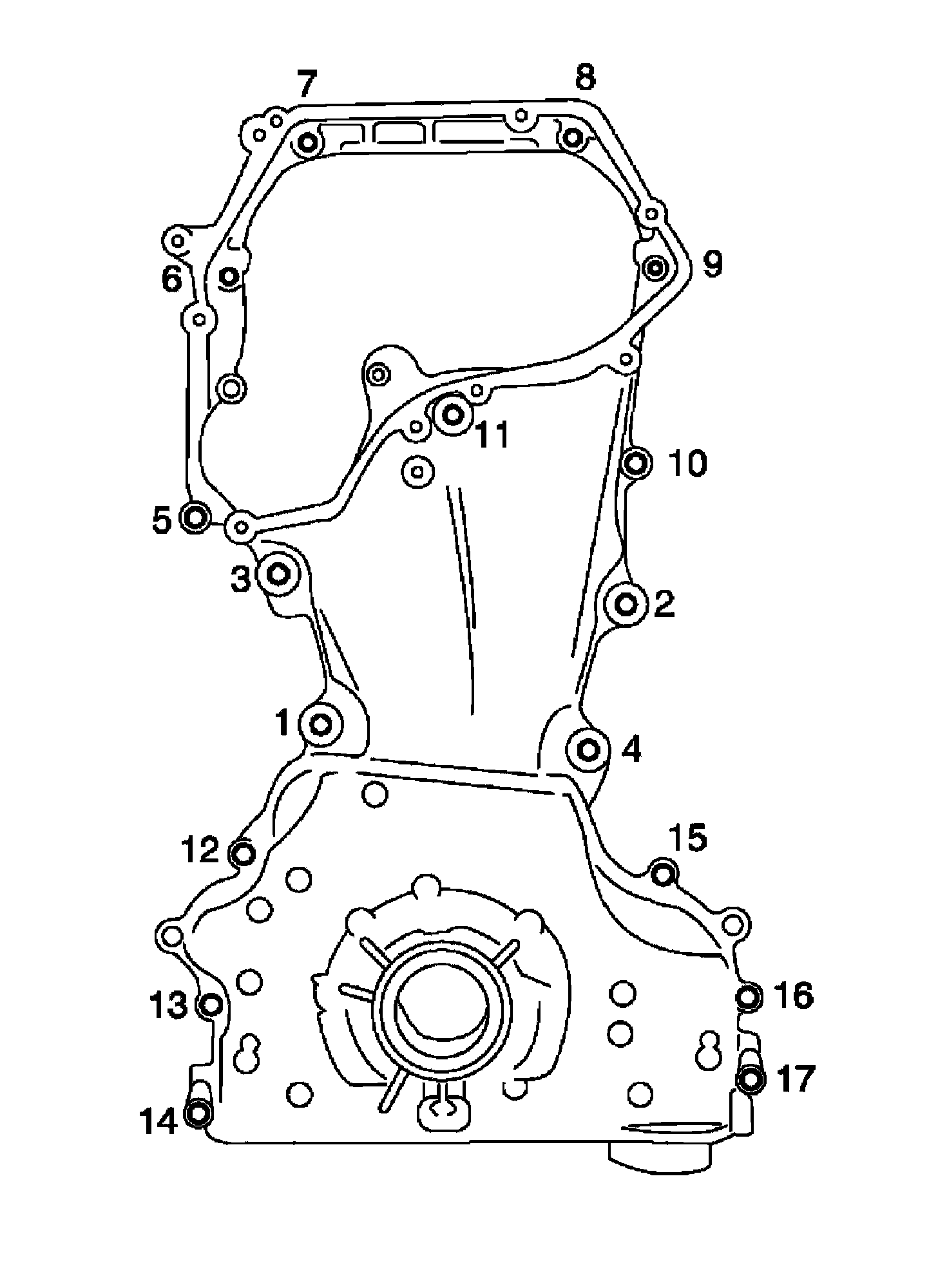
^ Use the following for locating M6 bolts.
Bolt position Bolt length
5,10,14,17: 45 mm (1.77 in)
Except the above: 20 mm (0.79 in)
(Except 1 through 4)
^ Tighten bolts to the specified torque.
Bolt position Torque specification
5 through 17: 12.8 Nm (1.3 kg-m, 9 ft-lb)
1 through 4: 49.0 Nm (5.0 kg-m, 36 ft-lb)
12) After all bolts are tightened, retighten them to the specified torque in numerical order as shown.
CAUTION:
Be sure to wipe off any excessive liquid gasket leaking to surface for fitting oil pan.
13) Install chain guide between camshaft sprockets.
14) Install O-rings to the camshaft sprocket (INT) insertion points on backside of intake valve timing control cover.
15) Install O-ring to front cover.
16) Apply a continuous bead of liquid gasket using Tool to intake valve timing control cover as shown.
Tool number: WS39930000 ( - )
Use Genuine RTV Silicone Sealant or equivalent.
17) Tighten bolts in numerical order as shown.
18) Install intake valve timing control solenoid valve to intake valve timing control cover if removed.
19) Connect ground cables, and install harness clip.
20) Insert crankshaft pulley by aligning with crankshaft key.
^ When inserting crankshaft pulley with a plastic hammer, tap on its center portion (not circumference).
CAUTION:
Do not damage front oil seal lip section.
21) Tighten crankshaft pulley bolt using Tool.
Tool number: KV10112100 (BT-8653-A)
^ Secure crankshaft pulley using suitable tool, and tighten crankshaft pulley bolt.
a) Apply new engine oil to thread and seat surfaces of crankshaft pulley bolt.
b) Tighten crankshaft pulley bolt.
: 42.1 Nm (4.3 kg-m, 31 ft-lb)
c) Put a paint mark on crankshaft pulley, mating with any one of six easy to recognize angle marks on bolt flange.
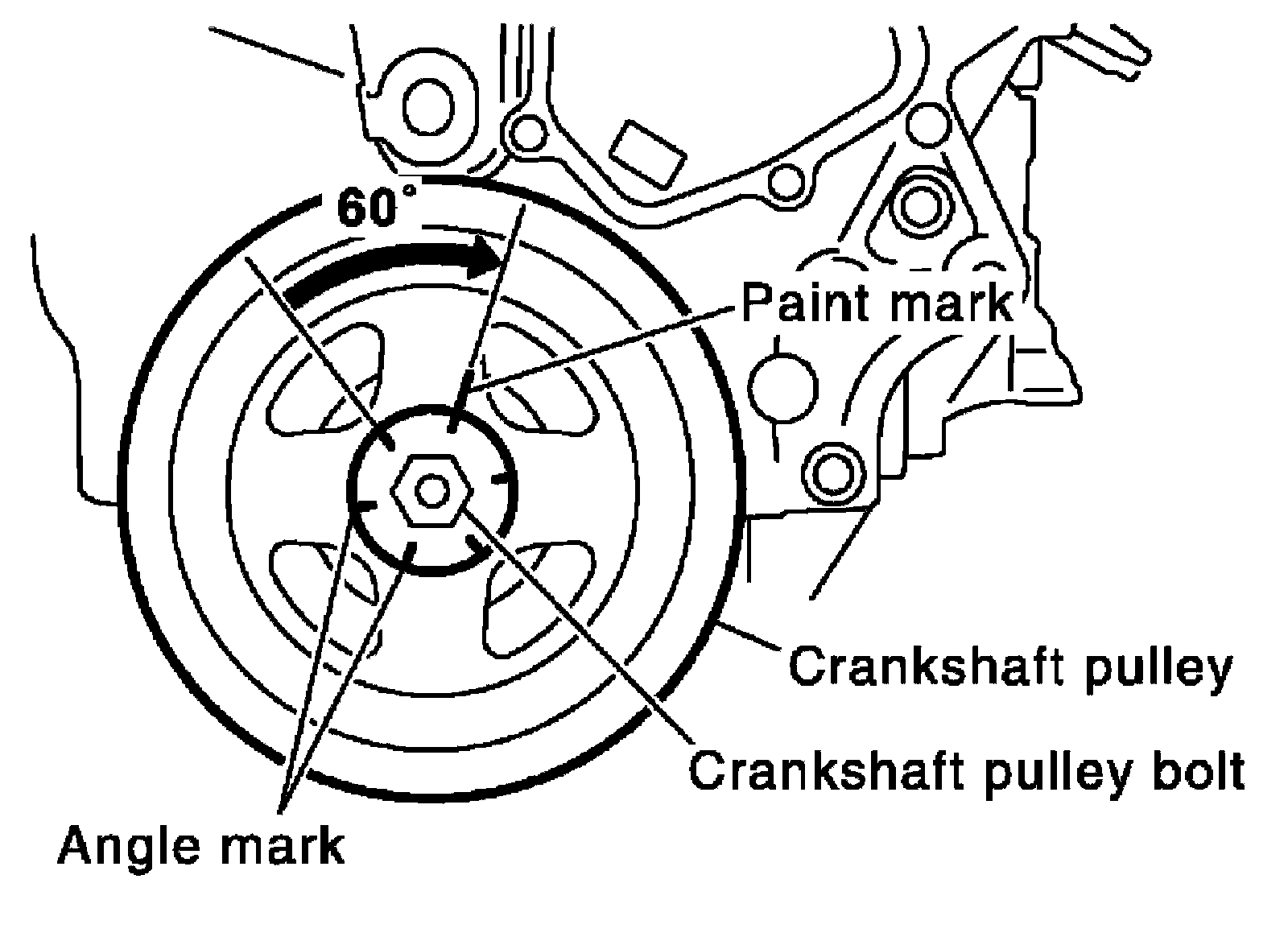
d) Turn another 60 degrees clockwise (angle tightening).
^ Check the tightening angle with movement of one angle mark.
22) Installation is in the reverse order of removal.
INSPECTION AFTER INSTALLATION
^ Before starting the engine, check oil/fluid levels including engine coolant and engine oil. If the levels are lower than required quantity, fill to the specified level.
^ Use procedure below to check for fuel leakage.
^ Turn ignition switch ON (with engine stopped). With fuel pressure applied to the fuel piping, check for fuel leakage at the connection points.
^ Start engine. With engine speed increased, check again for fuel leakage at connection points.
^ Run engine to check for unusual noise and vibration.
NOTE:
If hydraulic pressure inside timing chain tensioner drops after removal and installation, slack in the guide may generate a pounding noise during and just after engine start. However, this is normal. Noise will stop after hydraulic pressure rises.
^ Warm up engine thoroughly to make sure there is no leakage of fuel, exhaust gas, or any oil/fluids including engine oil and engine coolant.
^ Bleed air from passages in lines and hoses, such as in cooling system.
^ After cooling down the engine, again check oil/fluid levels including engine oil and engine coolant. Refill to specified level if necessary.
^ Summary of the inspection items: