Headlamp System
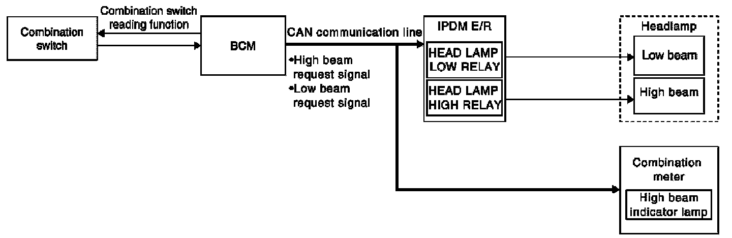
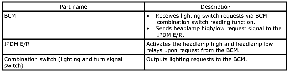
Headlamp: System DescriptionControl of the headlamp system operation is dependent upon the position of the lighting switch (combination switch). When the lighting switch is placed in the 2nd position, the BCM (body control module) receives input requesting the headlamps and park lamps to illuminate. This input is communicated to the IPDM E/R (intelligent power distribution module engine room) via the CAN communication lines. The CPU (central processing unit) of the IPDM E/R controls the headlamp high and headlamp low relay coils. When energized, these relays direct power to the respective headlamps, which then illuminate.
HIGH BEAM OPERATION/FLASH-TO-PASS OPERATION
With the lighting switch in the 2ND position and placed in HIGH position, the BCM receives input requesting the headlamp high beams to illuminate. The flash to pass feature can be used any time and also sends a signal to the BCM. This input is communicated to the IPDM E/R via the CAN communication lines. The CPU of the combination meter controls the ON/OFF status off the HIGH BEAM indicator. The CPU of the IPDM E/R controls the headlamp high relay coil which supplies power to the high beam headlamps.
The combination meter receives a high beam request signal (ON) via the CAN communication lines and turns the high beam indicator lamp ON.
Headlamp: Component Description
Headlamp: System Diagram