Valve Clearance: Service and Repair
Camshaft Valve ClearanceINSPECTION
Perform the following inspection after removal, installation or replacement of camshaft or valve related parts, or if there are unusual engine conditions due to changes in valve clearance over time (starting, idling or noise).
1) Remove rocker cover.
2) Remove engine undercover.
3) Remove radiator shroud (lower).
4) Measure the valve clearance as follows:
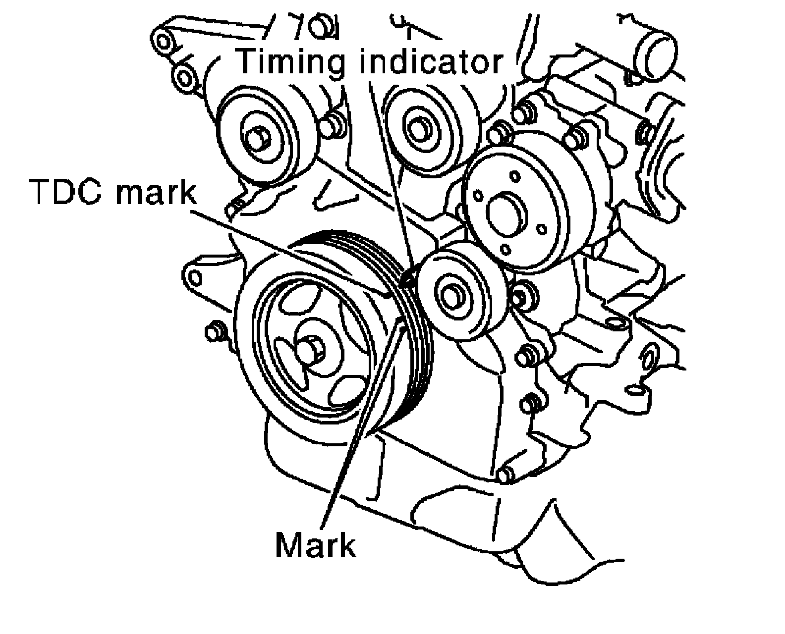
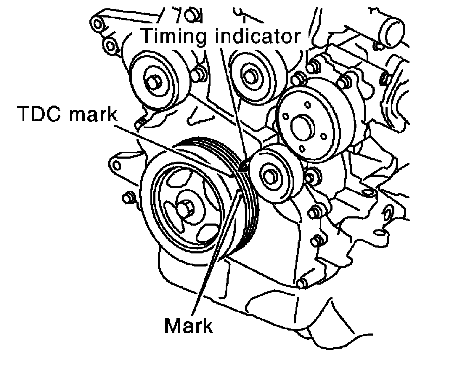
a) Set No. 1 cylinder at TDC of its compression stroke.
^ Rotate crankshaft pulley clockwise and align TDC mark to timing indicator on front cover.
^ Make sure that intake and exhaust cam noses of No. 1 cylinder are located as shown.
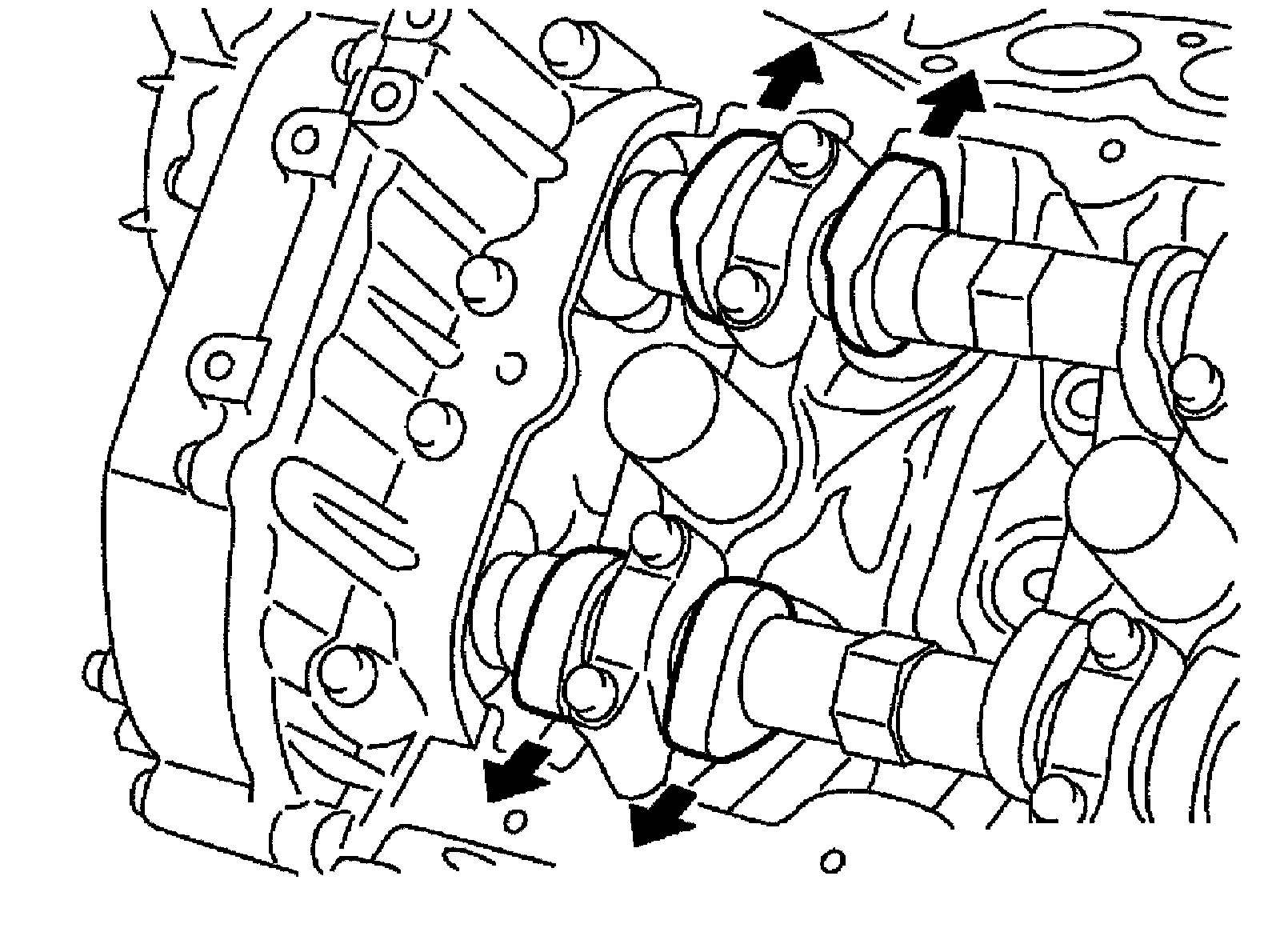
^ If not, rotate crankshaft one revolution (360°) and align as shown.
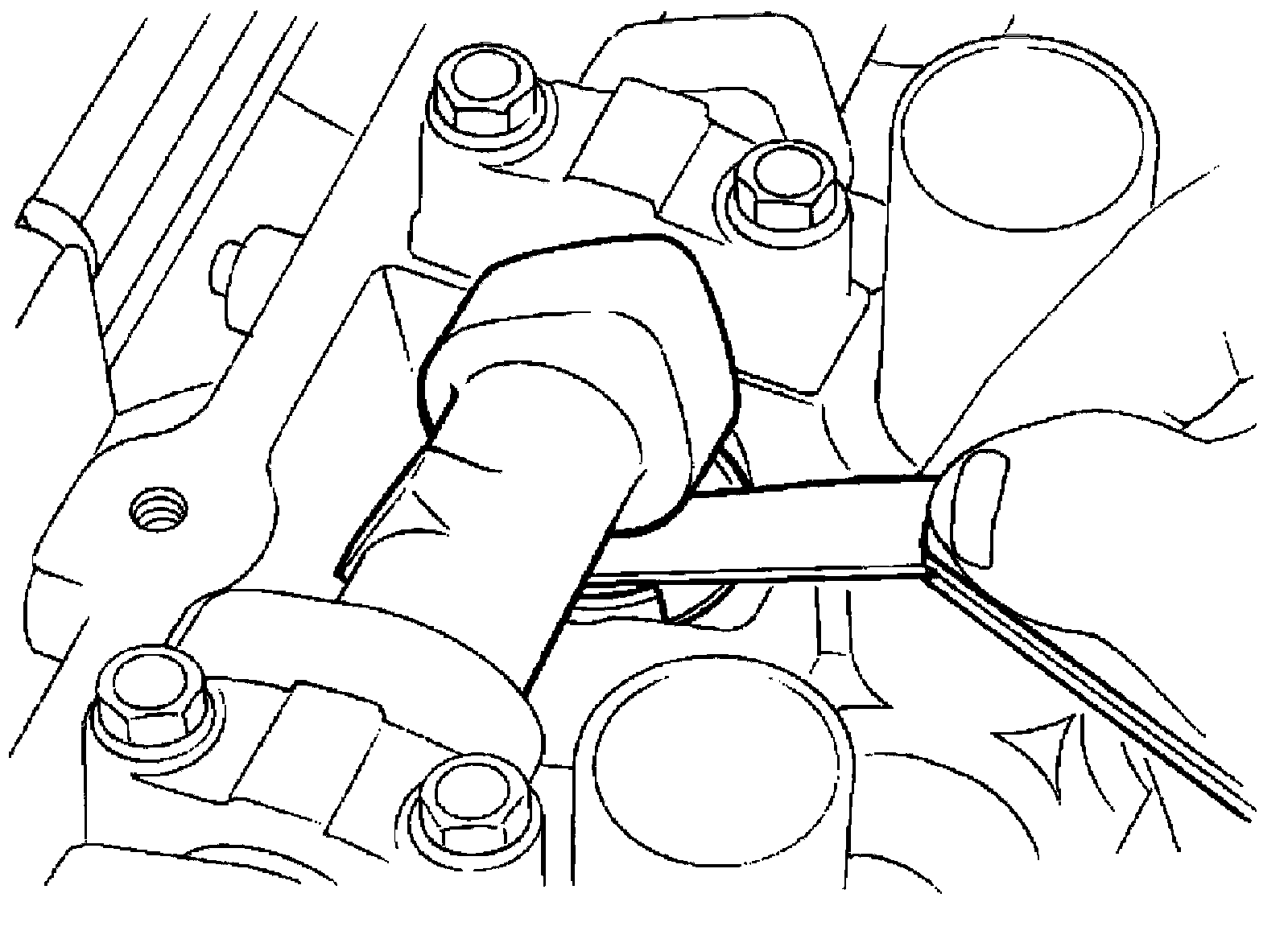
b) Use a feeler gauge, measure the clearance between valve lifter and camshaft.
Valve clearance:

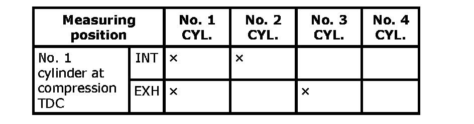
^ Measure the valve clearances at locations marked "x" as shown in the table below (locations indicated with black arrow shown) with feeler gauge.
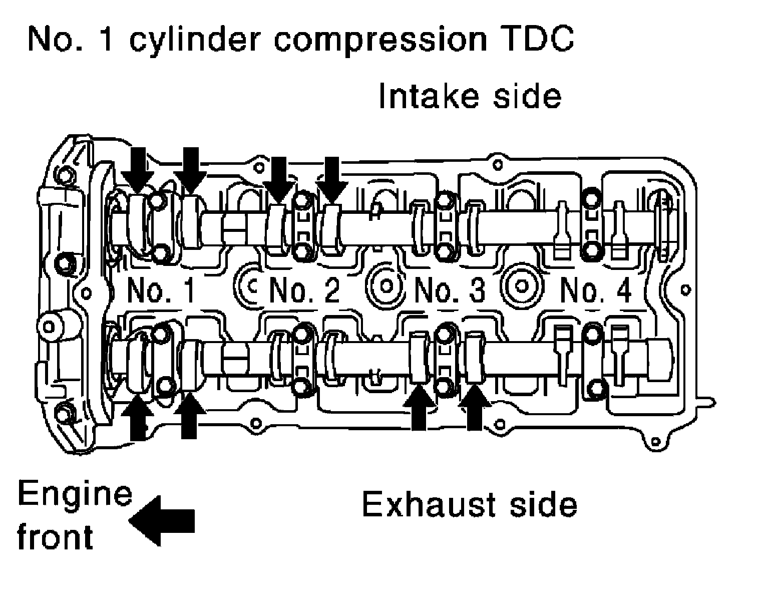
^ No. 1 cylinder compression TDC
c) Rotate crankshaft one revolution (360°) and align TDC mark to timing indicator on front cover.
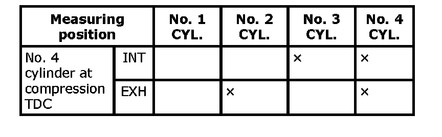
^ Measure the valve clearance at locations marked "x" as shown in the table below (locations indicated with black arrow shown) with feeler gauge.
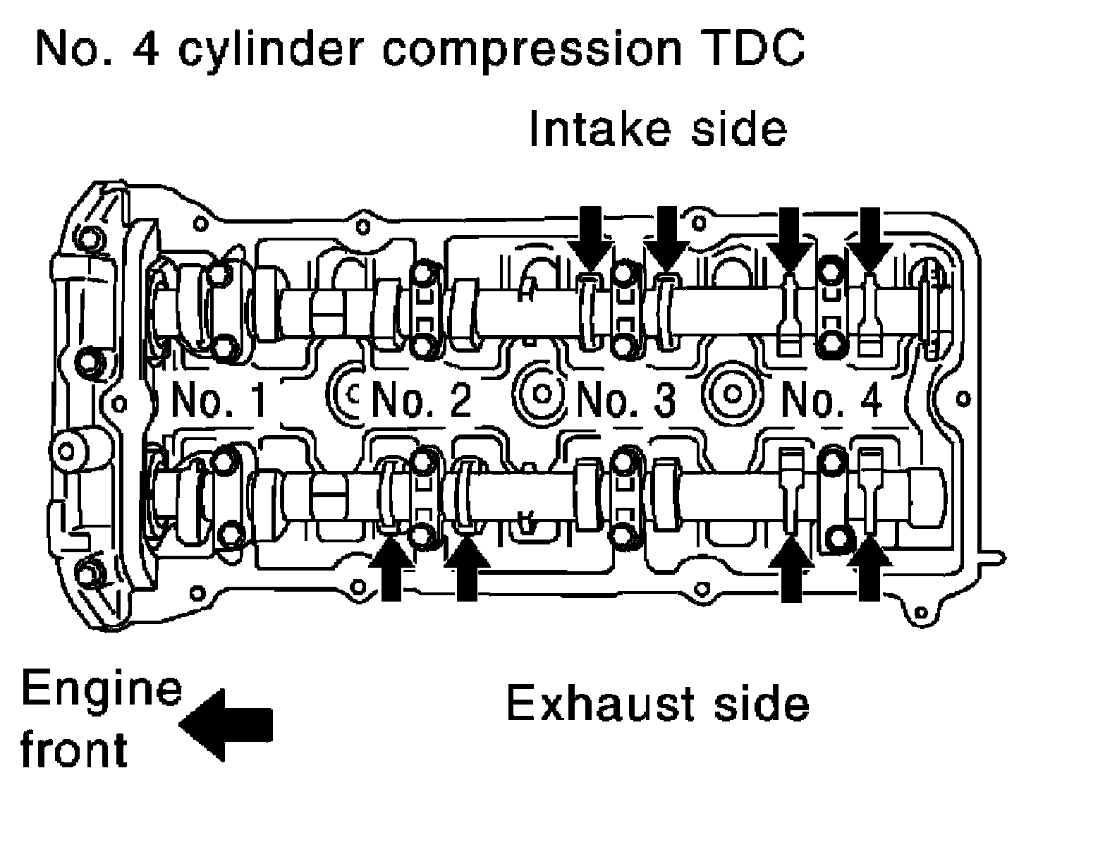
^ No. 4 cylinder compression TDC
5) If out of standard, perform adjustment.
ADJUSTMENT
^ Perform adjustment depending on selected head thickness of valve lifter.
1) Measure the valve clearance.
2) Remove camshaft.
3) Remove valve lifters at the locations that are out of the standard.
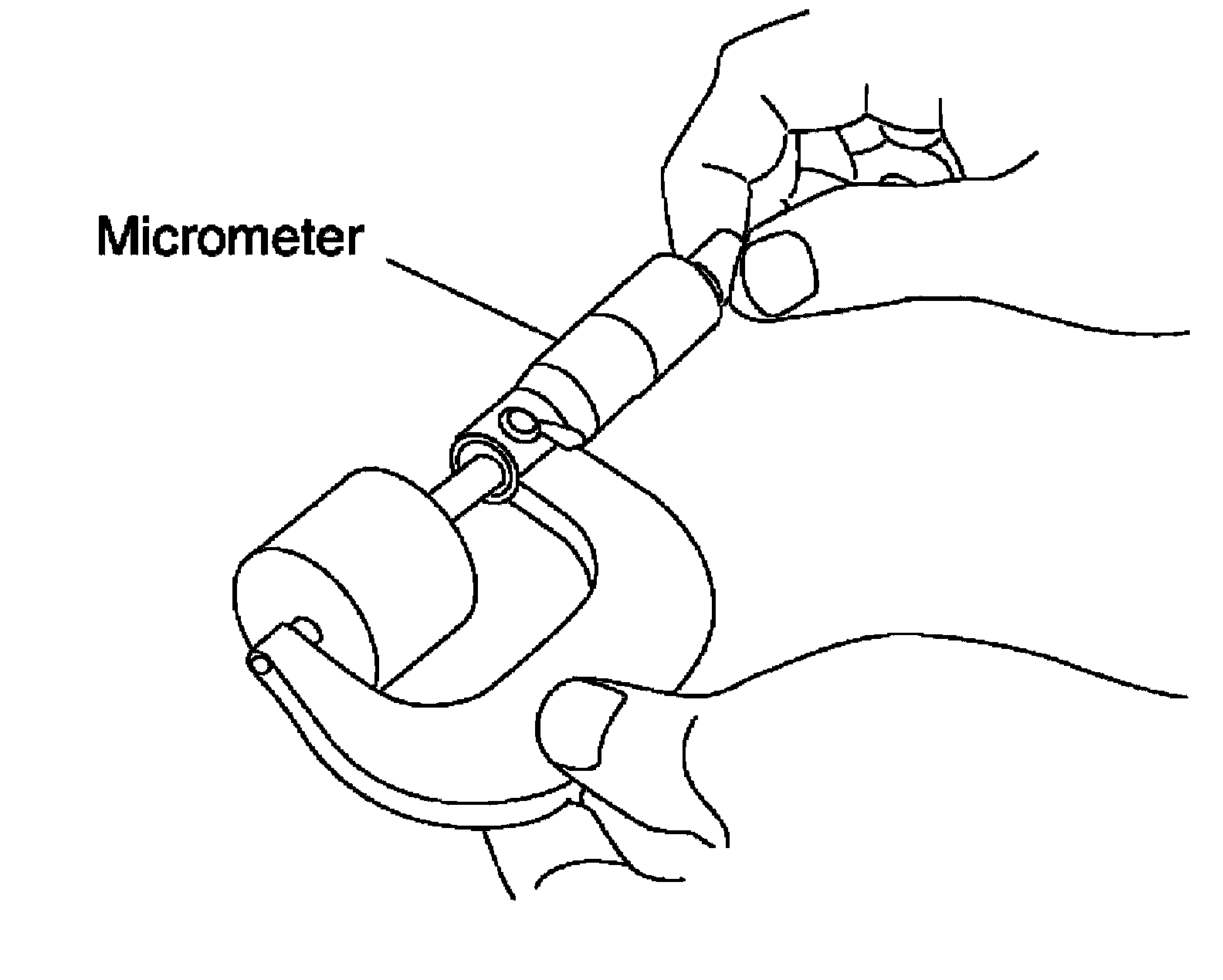
4) Measure the center thickness of the removed valve lifters with a micrometer.
5) Use the equation below to calculate valve lifter thickness for replacement.
Valve lifter thickness calculation: t = t1 + (c1 - c2)
t = Valve lifter thickness to be replaced
t1 = Removed valve lifter thickness
c1 = Measured valve clearance
c2 = Standard valve clearance:
Intake: 0.28 mm (0.011 in)
Exhaust: 0.30 mm (0.012 in)
^ Thickness of new valve lifter can be identified by stamp marks on the reverse side (inside the cylinder).
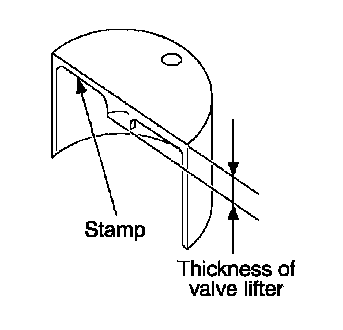
Stamp mark "696" indicates 6.96 mm (0.2740 in) in thickness.
NOTE:
Available thickness of valve lifter: 26 sizes range 6.96 to 7.46 mm (0.2740 to 0.2937 in) in steps of 0.02 mm (0.0008 in) (when manufactured at factory).
6) Install the selected valve lifter.
7) Install camshaft.
8) Manually rotate crankshaft pulley a few rotations.
9) Make sure that the valve clearances for cold engine are within specifications by referring to the specified values.
10) Installation of the remaining components is in the reverse order of removal.
11) Start the engine, and check for unusual noise and vibration.