Inspection of P/S Control Module and Its Circuits
Inspection of P/S Control Module and Its Circuits
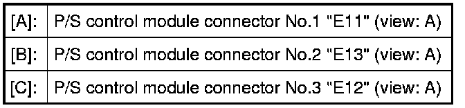
The P/S control module (1) and its circuits can be checked at the P/S control module wiring couplers (2) by measuring voltage and resistance.
NOTE:
If you connect a voltmeter or ohmmeter directly to the P/S control module by disconnecting the P/S control module connectors, you can damage the P/S control module.
Never connect a voltmeter or an ohmmeter directly to any terminal on the P/S control module by disconnecting the P/S control module connectors.

Voltage Check
1) Remove console box.
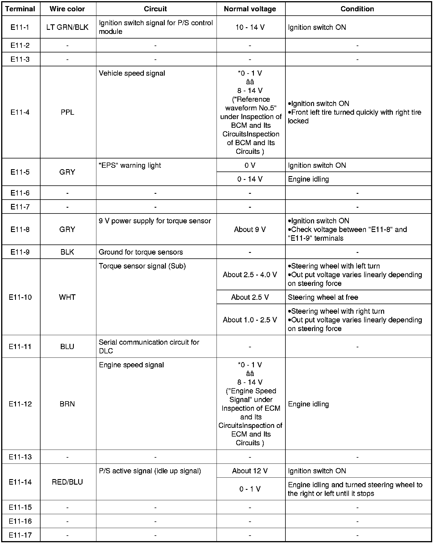
2) Check for voltage at each terminal with connectors connected to the P/S control module.
NOTE:
As each terminal voltage is affected by the battery voltage, confirm if the battery voltage is 11 V or more when ignition switch is ON.

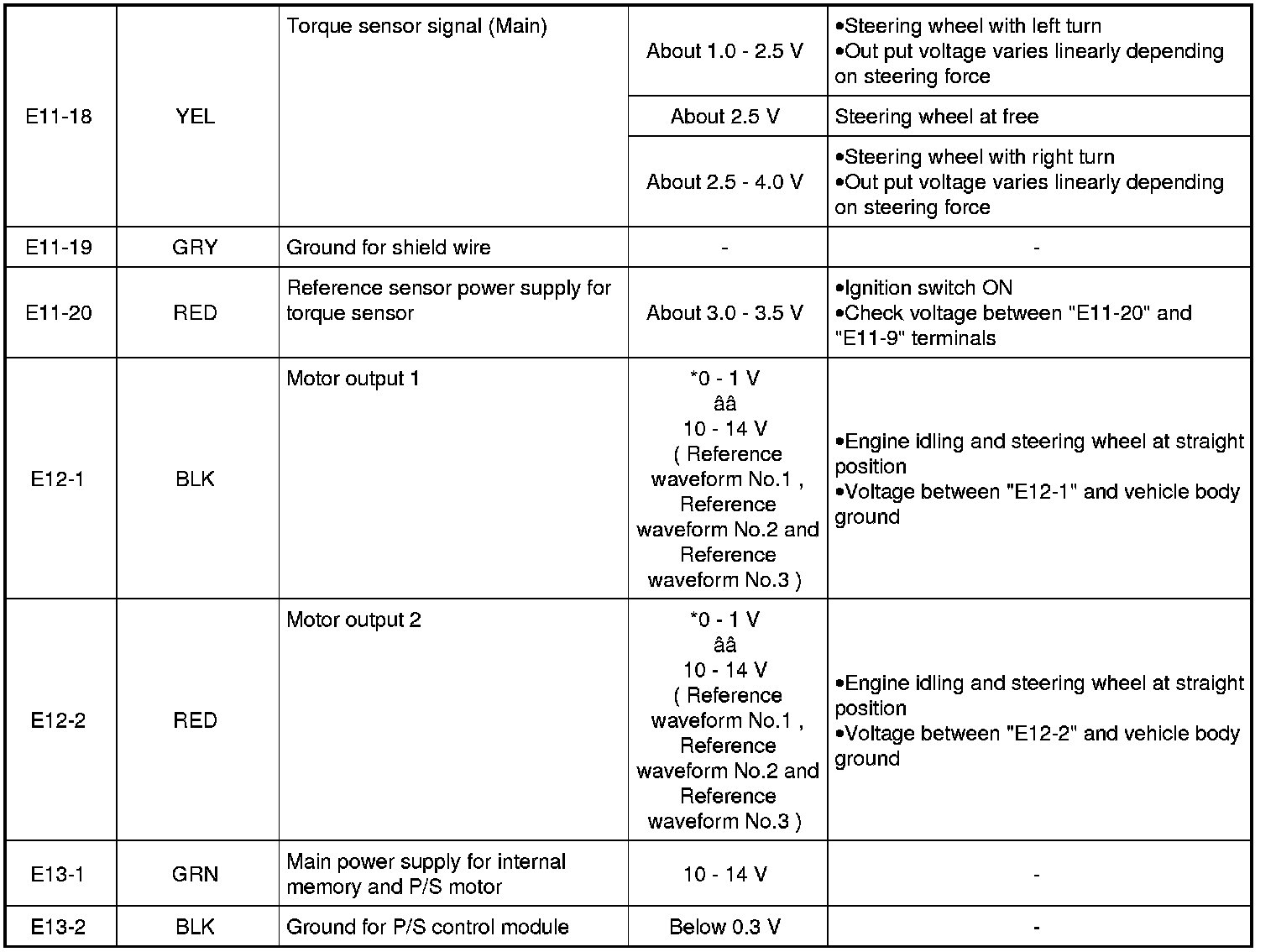
NOTE:
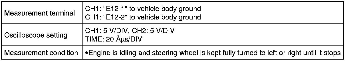
*: The voltage of this circuit may not be checked by voltmeter. If so, use oscilloscope.
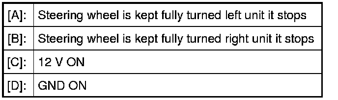
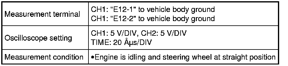
Reference waveform No.1
Motor output signal 1 (1), Motor output signal 2 (2), with engine idling

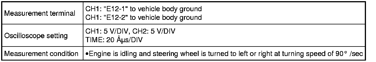
Reference waveform No.2
Motor output signal 1 (1), Motor output signal 2 (2), with engine idling

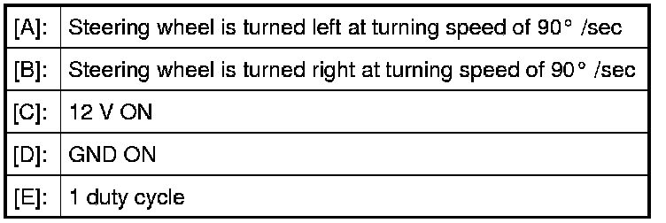
Reference waveform No.3
Motor output signal 1 (1), Motor output signal 2 (2), with engine idling