Part 2
A/C System Inspection at ECM
Inspection of ECM and Its Circuits
Precautions for ECM Circuit Inspection Precautions for ECM Circuit Inspection
NOTE:
- The connectors of the ECM are watertight. If tester probes are directly connected to any of the connectors when checking the ECM and its circuits, the watertight performance of the connector will be affected, possibly resulting in corrosion of connector terminals and damage to electrical circuits.
Always use the special tool when checking the ECM and its circuits. Connect tester probes only to the special tool's connectors.
- If you connect a voltmeter or ohmmeter directly to control module terminals by removing control module connectors, you can damage the control module.
Never connect a voltmeter or an ohmmeter directly to any terminal of control module by disconnecting control module connectors.
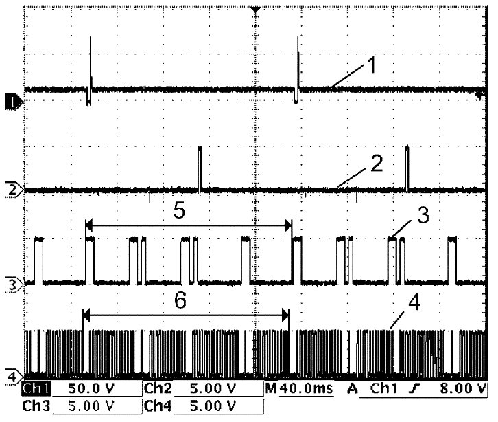
Fuel Injector No.4 Signal and Ignition Coil No.4 Signal
Fuel injector No.4 signal (1):

Ignition coil No.4 signal (2):

CMP sensor signal (3):

CKP sensor signal (4):

Measurement condition
- Engine: Idle speed after warm-up

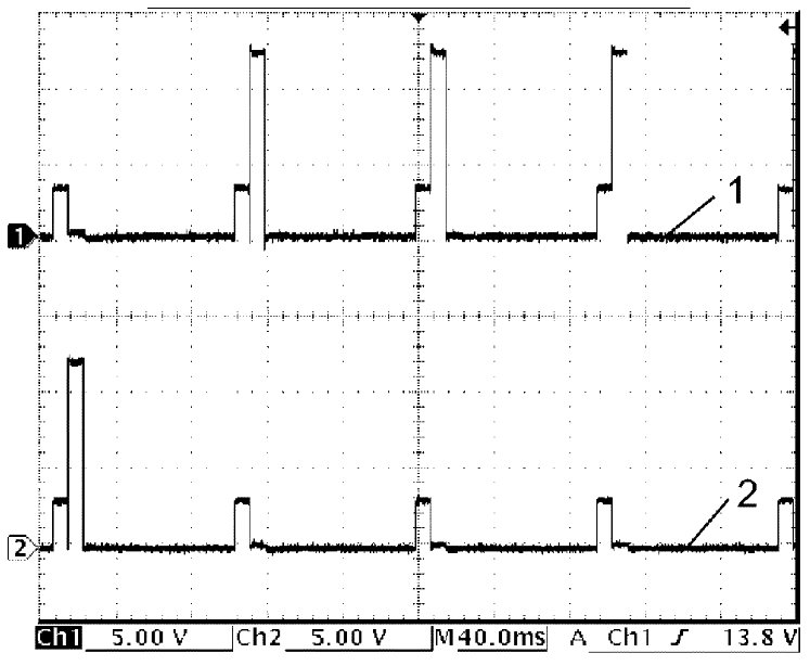
Generator Control Signal and Generator Field Coil Monitor Signal
Generator field coil monitor signal (1):

Generator control signal (2):

Measurement condition
- Engine: Idle speed after warm-up
- Lighting switch: OFF
- A/C switch: OFF
- Blower speed selector: OFF
- Rear defogger switch: OFF

Measurement condition
- Engine: Idle speed after warm-up
- Lighting switch: ON
- A/C switch: ON
- Blower speed selector: 4th position
- Rear defogger switch: ON

HO2S Signal and HO2S Heater Signal
HO2S signal (1):

HO2S heater signal (2):

Measurement condition
- Engine: Idle speed after warm-up

Measurement condition
- Engine: Racing after warm-up


Ignition Coil Signal

Measurement condition
- Engine: Idle speed after warm-up

MAF Sensor Signal

Measurement condition
- Engine: Idle speed after warm-up


A/F Sensor Heater Signal

Measurement condition
- Engine: Idle speed after warm-up


OCV Signal

Measurement condition
- OCV: OFF -> ON (using "Active Test of SUZUKI scan tool")
A/F Sensor Signal

Measurement condition
- Engine: Racing after warm-up


IMT Valve Actuator Signal
IMT valve actuator signal (close) (1):

IMT valve actuator signal (open) (2):

Measurement condition
- Ignition switch: ON

Measurement condition
- IMT valve: CLOSE -> OPEN (using "Active Test of SUZUKI scan tool)

- IMT valve: OPEN -> CLOSE (using "Active Test of SUZUKI scan tool)
Throttle Actuator Signal

Measurement condition
- Ignition switch: ON
- Accelerator pedal: Idle position

Measurement condition
- Ignition switch: ON
- Accelerator pedal: Fully depressed position

CKP Sensor Signal and CMP Sensor Signal
CMP sensor signal (1):

CKP sensor signal (2):

Measurement condition
- Engine: Idle speed after warm-up

Knock Sensor Signal

Measurement condition
- Engine: Running at 4,000 rpm after warmed up

EVAP Canister Purge Valve Signal

Measurement condition
- EVAP canister purge valve: 10% open (using "Active Test of SUZUKI scan tool)

Engine speed signal

Measurement condition
- Engine: Idle speed after warm-up

CAN Communication Signal
CAN communication signal (High) (1):

CAN communication signal (Low) (2):

Measurement condition
- Engine: Stop
- Ignition switch: ON
