Front Wheel Hub, Steering Knuckle and Wheel Bearing Removal and Installation
Front Wheel Hub, Steering Knuckle and Wheel Bearing Removal and Installation
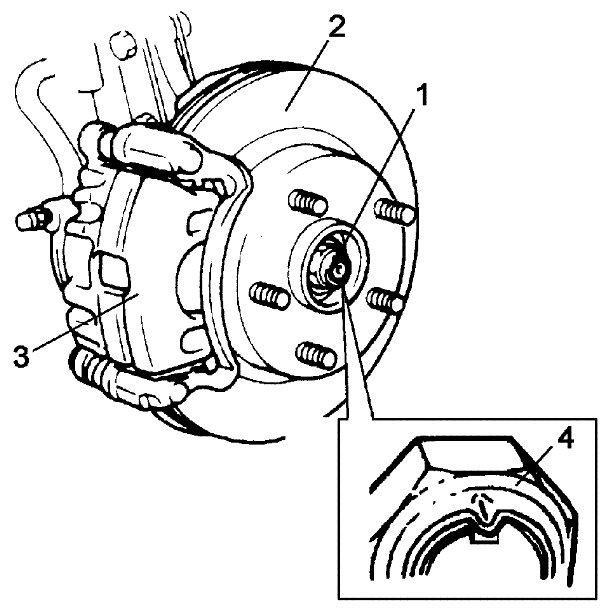
Front Wheel Hub and Steering Knuckle Components
NOTE:
- If the steering knuckle assembly is not removed and installed carefully, the drive shaft dust cover and brake dust cover may damage the dust boots of the suspension arm joints.
When removing and installing the steering knuckle assembly, be careful not to damage the suspension arm joint dust boots.
- Reusing the removed wheel bearing and circlip can lead to abnormal noise, vibration or other abnormal conditions.
Never reuse the wheel bearing and circlip.
Removal
1) Hoist vehicle and remove wheel.
2) Uncaulk drive shaft nut (1).
3) Depress foot brake pedal and hold it. Remove drive shaft nut (1).
NOTE:
Once you remove the drive shaft nut (1), it will no longer have the necessary fastening performance.
Never reuse the drive shaft nut.

4) Remove caliper carrier bolts and then remove caliper (1) with carrier.
NOTE:
Hang removed caliper with a wire hook or the like (3) so as to prevent brake hose (4) from bending, twisting or tension.
Do not depress brake pedal during caliper removal.
Do not operate brake pedal with caliper removed.
5) Pull brake disc (2) off by using two M8 bolts.

6) Pull out wheel hub (1) with special tools.
Special Tool
(A): 09943-17912
(B): 09942-15511
NOTE:
If the wheel hub is removed and reinstalled without replacing the wheel bearing with a new one, the wheel hub bearing may not operate properly.
Whenever the wheel hub is removed, replace the wheel bearing with a new one.

7) Disconnect tie-rod end from steering knuckle referring to Removal and Installation Tie-Rod End Removal and Installation:Hydraulic Type or Removal and Installation Tie-Rod End Removal and Installation:Electric Type.
8) Remove wheel speed sensor (1) from knuckle.

9) Loosen strut bracket nuts (1).
10) Remove ball joint bolt (4) and washer (3).
11) Remove strut bracket bolts (5) from strut bracket and then steering knuckle (2).
NOTE:
Reusing the removed strut bracket nut can cause it to loosen, because the pre-coated friction stabilizer can come off during removal.
Never reuse the strut bracket nut.


12) Uncaulk and remove dust cover (1).

13) Remove circlip from knuckle.
14) Using hydraulic press (1) and special tool, remove wheel bearing.
Special Tool
(A): 09913-75510
(B): 09943-37910

15) Remove wheel bearing outside inner race (1).
Special Tool
(A): 09913-65810
(B): 09913-85230

16) Remove hub bolts (1) with copper hammer or hydraulic press.
NOTE:
Removing the hub bolts will break the rotation preventing projections on the hub bolts.
Avoid removing the hub bolts unless their replacement is absolutely necessary. If the hub bolts are removed, never reuse the bolts. Replace them with new bolts.

Installation
Suspension Arm / Steering Knuckle Check
1) Face grooved rubber seal side (1) of new wheel bearing (2) upward as shown in figure and press-fit it into knuckle (3) using special tools.
Special Tool
(A): 09913-75510
(B): 09944-78220
(C): 09925-14520


2) Install new circlip (1).

3) Insert new hub bolt (1) in hub hole. Rotate hub bolt slowly to assure that serrations are aligned with those made by original bolt.

4) Drive in dust cover so that dimensions "a" and "b" become equal as shown in figure.
NOTE:
The dust cover can easily get deformed.
Be careful when driving the dust cover onto the knuckle.

5) Caulk more than 6 places with a punch.

6) Using special tool and hydraulic press, press fit wheel hub (1) into wheel bearing (2) (Face grooved rubber seal side to wheel hub).
Special Tool
(A): 09913-75510

7) Apply grease lightly to end face of inner ring (1).
"A" Grease: 99000-25121 (SUZUKI Super Grease H)
NOTE:
If the encoder (2) section of the wheel bearing is contaminated with grease, the wheel speed sensor may not sense the wheel speed correctly.
Avoid applying grease to the encoder section of the wheel bearing.

8) Install steering knuckle with wheel hub and bearing (1) so that foreign material should not enter wheel speed sensing point "a".


9) Install ball joint bolt (1), washer (2), strut bracket bolts (4) and new nuts (3) from the direction shown in figure.
10) Tighten suspension arm ball joint bolt (2) to specified torque.
Tightening torque
Suspension arm ball joint bolt (a): 60 Nm (6.0 kgf-m, 43.5 lbf-ft)
11) Tighten new strut bracket nuts (3) to specified torque.
Tightening torque
Strut bracket nut (b): 140 Nm (14.0 kgf-m, 101.5 lbf-ft)


12) Install wheel speed sensor (1).
Tightening torque
Wheel speed sensor mounting bolt (a): 11 Nm (1.1 kgf-m, 8.0 lbf-ft)

13) Connect tie-rod end to steering knuckle referring to Removal and Installation Tie-Rod End Removal and Installation:Hydraulic Type or Removal and Installation Tie-Rod End Removal and Installation:Electric Type.
14) Install brake disc (2) and brake caliper (3).
15) Tighten caliper carrier bolt to specified torque referring to Front Brake Disc Removal and Installation Front Brake Disc Removal and Installation.
16) Depress foot brake pedal and hold it there.
Tighten new drive shaft nut (1) to specified torque referring to Locations Front Drive Shaft Assembly Component Location:Front.
17) Caulk drive shaft nut (4) as shown.
NOTE: - Once you remove the drive shaft nut (1), it will no longer have the necessary fastening performance.
Never reuse the drive shaft nut.
- If the drive shaft nut is calked at an improper point, the nut may work loose.
Be sure to calk the drive shaft nut only at the point corresponding to the groove in the drive shaft.
18) Tighten wheel nuts to specified torque referring to Removal and Replacement Wheel (with Tire) Removal and Installation.
19) Confirm front wheel alignment referring to Front Wheel Alignment Inspection and Adjustment Front Wheel Alignment Inspection and Adjustment.