Removal and Replacement
REMOVAL1. REMOVE FRONT DOOR SCUFF PLATES
a. Standard cab:
Remove the 10 screws and front door scuff plates.
b. Access cab:
Remove the 8 screws and front door scuff plates.
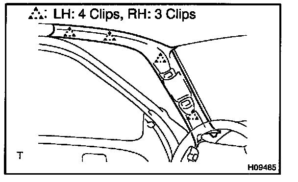
2. REMOVE COWL SIDE TRIMS
Remove the 2 clips and cowl side trims.
3. REMOVE ASSIST GRIPS

a. Using a screwdriver, remove the caps.
HINT: Tape the screwdriver tip before use.
b. Driver's side:
Using a torx driver, remove the 2 torx screws and assist grip.
Torx driver: T30 (Part No.09041-00030 or locally manufactured tool)
c. Passenger's side:
Using a torx driver, remove the 4 torx screws and 2 assist grips.
Torx driver: T30 (Part No.09041-00030 or locally manufactured tool)
4. REMOVE FRONT PILLAR GARNISH
a. Using a screwdriver, remove the front pillar garnish.
HINT: Tape the screwdriver tip before use.
b. Employ the same manner described above to the other side.
5. REMOVE STEERING WHEEL PAD
6. REMOVE STEERING WHEEL
7. REMOVE STEERING COLUMN COVERS
8. REMOVE COMBINATION SWITCH
Disconnect the 4 connectors, remove the 3 screws and combination switch.
9. REMOVE LOWER FINISH PANEL

a. Remove the 2 screws and hood lock release lever.
b. Remove the 4 bolts and lower finish panel.

10. REMOVE SWITCH BASE
Using a screwdriver, lift up the switch base and remove it.
HINT: Tape the screwdriver tip before use.
11. REMOVE NO. 2 HEATER TO REGISTER DUCT
12. REMOVE STEERING COLUMN

13. REMOVE CLUSTER FINISH PANEL
Remove the 2 screws and cluster finish panel.
14. REMOVE COMBINATION METER
a. Remove the 4 screws.
b. Remove the combination meter and disconnect the 4 connectors.
15. REMOVE INTEGRATION CONTROL PANEL

a. Remove the 3 control knobs.
b. Remove the 5 screws.
c. Remove the integration control panel by pulling the portions indicated by arrows in the illustration.
d. Disconnect the connectors.
16. REMOVE RADIO TUNER ASSEMBLY

a. Disconnect the connector.
b. Remove the 4 bolts and radio tuner assembly.
17. REMOVE HEATER CONTROL ASSEMBLY
18. DISCONNECT FRONT PASSENGER AIRBAG ASSEMBLY CONNECTOR
NOTE: When handling the airbag connector, take care not to damage the airbag wire harness.

a. Using a clip remover, disengage the connector clamp.
b. Disconnect the connector as shown in the illustration.

19. REMOVE GLOVE COMPARTMENT DOOR
Remove the 2 screws and glove compartment door.
20. REMOVE LOWER NO. 2 FINISH PANEL
Remove the 3 screws and lower No. 2 finish panel.

21. REMOVE LOWER CENTER COVER
Remove the 2 clips and lower center cover.
22. REMOVE LOWER INSTRUMENT COVER

a. Remove the 4 bolts and screw.
b. Using a screwdriver, remove the lower instrument cover.
HINT: Tape the screwdriver tip before use.
23. REMOVE PASSENGER AIRBAG ASSEMBLY

a. Remove the 2 bolts holding the front passenger airbag assembly and instrument panel.
Torque: 5.0 N.m (51 kgf.cm, 44 in.lbf)
b. Remove the 2 bolts holding the front passenger airbag assembly and instrument panel reinforcement.
Torque: 20 N.m (204 kgf.cm, 15 ft.lbf)
CAUTION:
- Do not store the front passenger airbag assembly with the airbag deployment side facing down.
- Never disassemble the front passenger airbag assembly.
24. w/ Rear console box:
REMOVE REAR CONSOLE BOX
a. Using a screwdriver, remove the console box pocket.
HINT: Tape the screwdriver tip before use.
b. Remove the 4 bolts and rear console box.
25. REMOVE NO. 4 HEATER TO REGISTER DUCT
26. REMOVE INSTRUMENT PANEL

a. Remove the nut.
b. Disconnect the connectors and remove the instrument panel.
27. REMOVE CENTER HEATER TO REGISTER DUCT
28. REMOVE INSTRUMENT PANEL REINFORCEMENT

a. Disconnect the connectors.
b. Remove the screw and running light relay.
c. Remove the 3 bolts, nut and No. 1 brace.
d. Remove the bolt, nut and No. 2 brace.
e. Remove the 3 bolts, 4 nuts and instrument panel reinforcement.
INSTALLATION
Installation is in the reverse order of removal.