Installation


INSTALLATION
1. INSTALL RH EXHAUST MANIFOLD TO CYLINDER HEAD

a. Place a new gasket on the cylinder head with the white painted marks facing the manifold side.
NOTICE: Be careful of the installation direction.

b. Install the exhaust manifold with 8 new nuts. Uniformly tighten the nuts in several passes.
Torque: 44 Nm (450 kgf-cm, 32 ft. lbs.)
c. Install the heat insulator with the 4 bolts.
Torque: 7.5 Nm (80 kgf-cm, 66 inch lbs.)
2. INSTALL LH EXHAUST MANIFOLD TO CYLINDER HEAD

a. Place a new gasket on the cylinder head with the white painted marks facing the manifold side.
NOTICE: Be careful of the installation direction.

b. Install the exhaust manifold with 8 new nuts. Uniformly tighten the nuts in several passes.
Torque: 44 Nm (450 kgf-cm, 32 ft. lbs.)
c. Install the heat insulator with the 4 bolts.
Torque: 7.5 Nm (80 kgf-cm, 66 inch lbs.)

3. PLACE CYLINDER HEADS ON CYLINDER BLOCK
a. Place 2 new cylinder head gaskets in position on the cylinder block.
HINT: On the rear side of the cylinder head gasket are marks to distinguish the LH and RH banks, a "2UR" mark for the RH bank and a "2UL" mark for the LH bank.
NOTICE: Be careful of the installation direction.
b. Place the 2 cylinder heads in position on the cylinder head gaskets.
4. INSTALL CYLINDER HEAD BOLTS
The cylinder head bolts are tightened in 3 progressive steps (steps (c) and (e)). If any cylinder head bolt is broken or deformed, replace it.
Cylinder Head Installation Sequence:

a. Apply a light coat of engine oil on the threads and under the heads of the cylinder head bolts.
b. Install the plate washer to the cylinder head bolt.

c. Install and uniformly tighten the 10 cylinder head bolts on one side of the cylinder head in several passes in the sequence shown, then do the other side as shown.
Torque: 32 Nm (325 kgf-cm, 24 ft. lbs.)
If any of the cylinder head bolts does not meet the torque specification, replace the cylinder head bolt.
NOTICE: Do not drop the plate washer for cylinder head bolt into portion A of the cylinder head. If dropped into portion A, the plate washer will pass through the cylinder head and cylinder block into the oil pan.

d. Mark the front of the cylinder head bolt with paint.
e. Retighten the cylinder head bolts by 90° in the numerical order shown.
f. Retighten the cylinder head bolts by an additional 90°.
Check that the painted mark is now at a 180° angle to front.
5. INSTALL SPARK PLUGS
6. ASSEMBLE EXHAUST CAMSHAFT

a. Install the camshaft gear spring, camshaft sub-gear and wave washer.
HINT: Attach the pins on the gears to the gear spring ends.

b. Using snap ring pliers, install the snap ring.
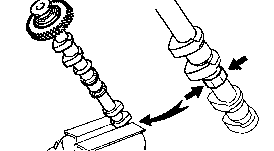
c. Mount the hexagon wrench head portion of the camshaft in a vise.
NOTICE: Be careful not to damage the camshaft.

d. Using SST, align the holes of the camshaft main gear and sub-gear by turning camshaft sub-gear counterclockwise, and temporarily install a service bolt.
SST 09960-10010 (09962-01000, 09963-00500)
e. Align the gear teeth of the main gear and sub-gear, and tighten the service bolt.
7. INSTALL CAMSHAFT HOUSING PLUGS
a. Remove any old packing (FIPG) material.

b. Apply seal packing to the camshaft housing plug grooves.
Seal packing: Part No. 08820-00080 or equivalent

c. Install the 2 camshaft housing plugs to the cylinder heads.
8. INSTALL CAMSHAFTS
NOTICE: Since the thrust clearance of the camshaft is small, the camshaft must be kept level while it is being installed. If the camshaft is not kept level, the portion of the cylinder head receiving the shaft thrust may crack or be damaged, causing the camshaft to seize or break. To avoid this, the following steps should be carried out.
a. Install the RH camshafts.
1. Apply MP grease to the thrust portion of the intake and exhaust camshafts.
2. Place the intake and exhaust camshafts.

3. Set the timing mark (1 dot mark) of the camshaft main gear at approximately 10° angle.

4. Remove any old packing (FIPG) material from front bearing cap.
5. Apply seal packing to the front bearing cap as shown in the illustration.
Seal packing: Part No. 08820-00080 or equivalent
- Install a nozzle that has been cut to a 1.5 mm (0.06 inch) opening.
- Parts must be assembled within 5 minutes of application. Otherwise the material must be removed and reapplied.
- Immediately remove nozzle from the tube and rein stall cap.
NOTICE: Do not apply seal packing to the front bearing cap grooves.

6. Install the front bearing cap.
HINT: Installing the front bearing cap will determine the thrust portion of the camshaft.
7. Install the other bearing cap in the sequence shown with the arrow mark facing forward.
HINT: Align the arrow marks at the front and rear of the cylinder head with the mark on the bearing cap.

8. Push in the camshaft oil seal.

9. Apply a light coat of engine oil on the threads and under the heads (D and E) of the bearing cap bolts.
HINT: Do not apply engine oil under the heads of the bearing cap bolt (A), (B) and (C).
10. Install the oil feed pipe the 22 bearing cap bolts as shown.
HINT: Each bolt length is indicated in the illustration.
Bolt length:
25 mm (0.98 inch) for A
38 mm (1.50 inch) for B
52 mm (2.05 inch) for C
72 mm (2.83 inch) for D
94 mm (3.70 inch) for E

11. Uniformly tighten the 22 bearing cap bolts in several passes, in the sequence shown.
Torque:
Bolt A: 7.5 Nm (80 kgf-cm, 69 inch lbs.)
Others: 16 Nm (160 kgf-cm, 12 ft. lbs.)

12. Boring the service bolt installed in the driven sub-gear upward by turning the hexagon wrench head portion of the camshaft with a wrench.
13. Remove the service bolt.
b. Install the LH camshafts.
1. Apply MP grease to the thrust portion of the intake and exhaust camshafts.
2. Place the intake and exhaust camshafts.

3. Engage the intake gear to the exhaust gear by meeting the timing marks (2 dot marks) on each gear.

4. Remove any old packing (FIPG) material.
5. Apply seal packing to the front bearing cap.
Seal packing: Part No. 08826-00080 or equivalent
- Install a nozzle that has been cut to a 1.5 mm (0.06 inch) opening.
- Parts must be assembled within 5 minutes of application. Otherwise the material must be removed and reapplied.
- Immediately remove nozzle from the tube and rein stall cap.
NOTICE: Do not apply seal packing to the front bearing cap grooves.

6. Install the front bearing cap.
HINT: Installing the front bearing cap will determine the thrust portion of the camshaft.
7. Install the other bearing cap in the sequence shown with the arrow mark facing forward.
HINT: Align the arrow marks at the front and rear of the cylinder head with the mark on the bearing cap.

8. Push in the camshaft oil seal.

9. Apply a light coat of engine oil on the threads and under the heads (D and E) of the bearing cap bolts.
HINT: Do not apply engine oil under the heads of the bearing cap bolt (A), (B) and (C).
10. Install the oil feed pipe and 22 bearing cap bolts as shown.
HINT: Each bolt length is indicated in the illustration.
Bolt length:
25 mm (0.98 inch) for A
38 mm (1.50 inch) for B
52 mm (2.05 inch) for C
72 mm (2.83 inch) for D
94 mm (3.70 inch) for E

11. Uniformly tighten the 22 bearing cap bolts in several passes, in the sequence shown.
Torque:
Bolt A: 7.5 Nm (80 kgf-cm, 69 inch lbs.)
Others 16 Nm (160 kgf-cm, 12 ft. lbs.)

12. Boring the service bolt installed in the driven sub-gear upward by turning the hexagon wrench head portion of the camshaft with a wrench.
13. Remove the service bolt.
9. CHECK AND ADJUST VALVE CLEARANCE
Turn the camshaft and position the cam lobe upward, and check and adjust the valve clearance.
10. INSTALL SEMI-CIRCULAR PLUGS
a. Remove any old packing (FIPG) material.

b. Apply seal packing to the semicircular plug grooves.
Seal packing: Part No. 08826-00080 or equivalent

c. Install the 4 semicircular plugs to the cylinder heads.

11. INSTALL CYLINDER HEAD COVERS
a. Remove any old packing (FIPG) material.
b. Apply seal packing to the cylinder heads as shown in the illustration.
Seal packing: Part No. 08826-00080 or equivalent
c. Install the gasket to the cylinder head cover.
d. Install the seal washer to the bolt.
e. Install the cylinder head cover with the 18 bolts. Uniformly tighten the bolts in several passes. Install the 2 cylinder head covers.
Torque: 6.0 Nm (60 kgf-cm, 53 inch lbs.)
12. INSTALL ENGINE HANGERS
Torque: 37 Nm (380 kgf-cm, 27 ft. lbs.)
13. INSTALL OIL DIPSTICK AND GUIDE FOR ENGINE

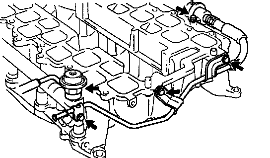
14. INSTALL REAR WATER BYPASS JOINT
a. Install 2 new gaskets to the cylinder head.
b. Install the 4 nuts holding the water bypass joint to the cylinder heads. Alternately tighten the nuts.
Torque: 18 Nm (185 kgf-cm, 13 ft. lbs.)

15. INSTALL FRONT WATER BYPASS JOINT
a. Install 2 new gaskets and the water bypass joint with the 4 nuts. Alternately tighten the nuts.
Torque: 18 Nm (185 kgf-cm, 13 ft. lbs.)
b. Connect the ECT sensor and water sender gauge connectors.
16. INSTALL WATER INLET AND INLET HOUSING ASSEMBLY
17. ASSEMBLE UPPER AND LOWER INTAKE MANIFOLDS
a. Install the 2 delivery pipes and 8 injectors.
b. Install new 2 gaskets, fuel pressure regulator and fuel pulsation damper.
c. Install the fuel return hose to the lower intake manifold with the 3 bolts.
d. Connect the fuel return hose to the fuel pressure regulator.

e. Install the EVAP pipe to the intake manifold with the 2 bolts.
f. w/o Hydraulic brake booster: Install new 2 gaskets, union and brake booster tube to the upper intake manifold with the bolt.
w/ Hydraulic brake booster: Install the plug to the upper intake manifold.

g. Install the accelerator cable clamp and VSV for EVAP to the upper intake manifold and and connect the EVAP hose.
h. Install a new gasket and upper intake manifold with the 13 bolts and 3 nuts.
i. Install the throttle body.
18. INSTALL INTAKE MANIFOLD ASSEMBLY

a. Place 2 new gaskets on the cylinder heads with white painted mark facing upward.
NOTICE: Align the port holes of the gasket and cylinder head. Be careful of the installation direction.

b. Place the intake manifold assembly on the cylinder heads.
c. Install and uniformly tighten the 6 bolts and 4 nuts in several passes.
Torque: 18 Nm (185 kgf-cm, 13 ft. lbs.)
d. Install the accelerator cable bracket to the intake manifold with the 2 nuts.
Torque: 18 Nm (185 kgf-cm, 13 ft. lbs.)

e. Install the throttle body cover bracket to the intake manifold and connect the DLC1 to the bracket.
Torque: 7.5 Nm (80 kgf-cm, 66 inch lbs.)
f. Install the wire bracket to the intake manifold.
g. Connect the engine wire to the engine hanger and wire bracket.
h. Install the engine wire to the LH No.1 timing belt rear plate.

i. Connect the wire protector to the rear water bypass joint and RH and LH cylinder heads with the 3 bolts.
j. Install the 2 ground cables to the RH and LH cylinder heads.
k. Install the guide for the A/T bracket to the LH cylinder head.

l. Connect the No.1 water bypass hose (from water inlet housing) from the throttle body.
m. Connect the 2 wire clamps to the throttle body.

n. Connect the 2 wire clamps to the wire clamp bracket on the RH delivery pipe.
o. Connect the accelerator cable to the throttle body.

19. CONNECT HOSES TO INTAKE MANIFOLD
a. Connect the vacuum hose to the pipe.
b. Connect the PCV hose to the PCV valve on the LH the cylinder head.
c. Connect the EVAP hose (from charcoal canister) to the VSV for EVAP.
d. Connect the EVAP hose (from charcoal canister) to the EVAP pipe on the intake manifold.
e. Connect the EVAP hose (from intake air connector) to the EVAP pipe on the intake manifold.
f. Connect the PS air hose to the intake manifold.
g. w/o Hydraulic brake booster: Connect the brake booster tube.
20. CONNECT CONNECTORS TO INTAKE MANIFOLD
a. Connect the throttle position sensor connector.
b. Connect the accelerator pedal position sensor connector.
c. Connect the throttle motor connector.
d. Connect the VSV connector for the EVAP.
e. Connect the 8 injector connectors.
f. Connect the ECT sensor connector.
g. Connect the water sender gauge connector.
h. Connect the 8 ignition coil connectors.
i. Connect the 2 heated oxygen sensor connectors.
21. CONNECT FUEL INLET HOSE AND FUEL RETURN HOSE
22. INSTALL TIMING BELT REAR PLATES
a. Install the RH timing belt rear plates. Install the No.1 timing belt rear plate to the cylinder head with the 3 bolts and stud bolt.
Torque: 7.5 Nm (80 kgf-cm, 66 inch lbs.)
b. Install the LH timing belt rear plates.
1. Connect the wire clamp to the No.1 timing belt rear plate.
2. Install the No.1 timing belt rear plate to the cylinder head with the 3 bolts.
Torque: 7.5 Nm (80 kgf-cm, 66 inch lbs.)
23. INSTALL THROTTLE BODY COVER
24. INSTALL IGNITION COILS
25. INSTALL OIL DIPSTICK AND GUIDE FOR A/T
26. INSTALL FRONT EXHAUST PIPE
27. INSTALL PS PUMP
28. INSTALL CAMSHAFT POSITION SENSOR
29. INSTALL CAMSHAFT TIMING PULLEYS
30. CONNECT TIMING BELT TO CAMSHAFT TIMING PULLEYS
31. CHECK ENGINE OIL LEVEL