Oil Pump Assembly Replacement
OIL PUMP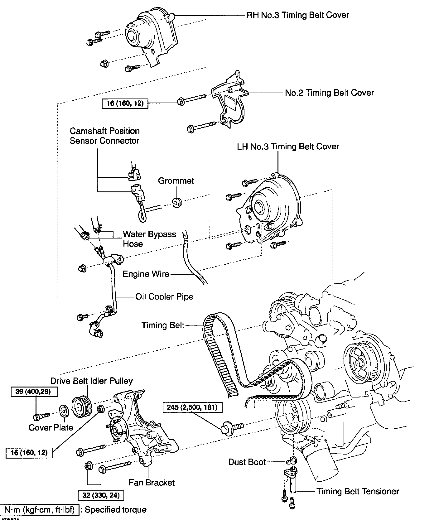
REMOVAL
HINT: When repairing the oil pump, the oil pan and strainer should be removed and cleaned.
1. REMOVE ENGINE FROM VEHICLE
2. INSTALL ENGINE TO ENGINE STAND FOR DISASSEMBLY
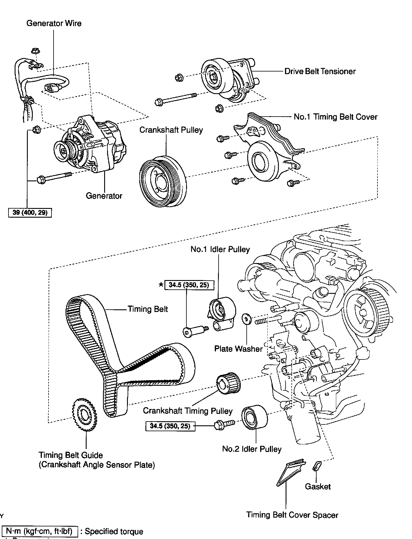
3. REMOVE TIMING BELT
4. REMOVE NO.1 IDLER PULLEY
5. REMOVE NO.2 IDLER PULLEY
6. REMOVE CRANKSHAFT TIMING PULLEY
7. REMOVE CRANKSHAFT POSITION SENSOR

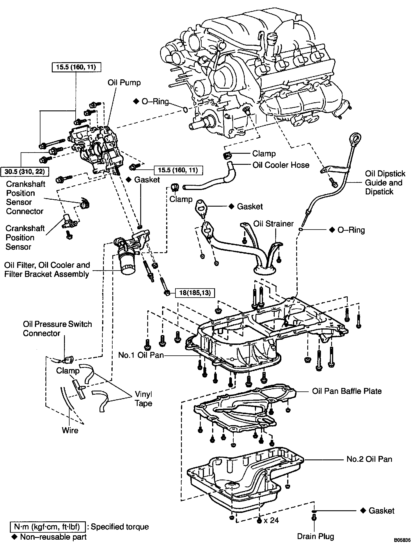
8. REMOVE OIL DIPSTICK AND GUIDE
a. Remove the bolt holding the oil dipstick to the LH cylinder head.
b. Pull out the dipstick guide together with the dipstick from the No.1 oil pan.
c. Remove the O-ring from the dipstick guide.

9. REMOVE OIL FILTER, OIL COOLER AND FILTER BRACKET ASSEMBLY
a. Disconnect the oil pressure switch connector.
b. Take out the vinyl tape, and disconnect the wire from the clamp.
c. Turn the clamp counterclockwise, and remove the clamp from the oil filter bracket.
d. Disconnect the oil cooler hose from the oil cooler.
e. Remove the 2 bolts, nut, the oil filter, oil cooler and filter bracket assembly.
f. Remove the gasket from the filter bracket.

10. REMOVE NO.2 OIL PAN
a. Remove the 24 bolts and 2 nuts.
b. Insert the blade of SST between the No.1 and No.2 oil pans, cut off applied sealer and remove the No.2 oil pan.
SST 09032-00100
NOTICE:
- Be careful not to damage the No.2 oil pan contact surface of the No.1 oil pan.
- Be careful not to damage the No.2 oil pan flange.

11. REMOVE OIL PAN BAFFLE PLATE
Remove the 7 bolts, 2 nuts and baffle plate.
12. REMOVE NO.1 OIL PAN

a. Remove the 18 bolts and 2 nuts.

b. Using a screwdriver, remove the No.1 oil pan by prying between the oil pan and cylinder block in the sequence shown.
NOTICE: Be careful not to damage the contact surface of the cylinder block and No.1 oil pan.

13. REMOVE OIL STRAINER
Remove the 2 bolt, 2 nuts, oil strainer and gasket.
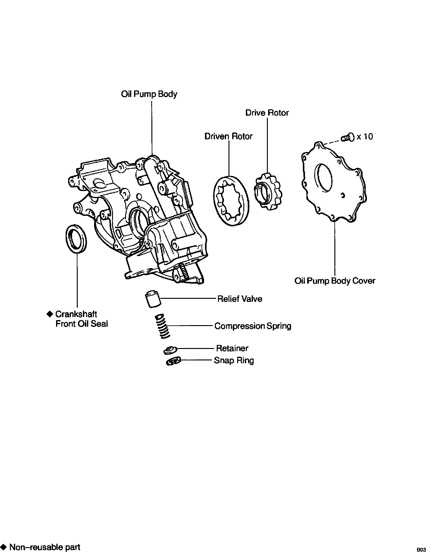
14. REMOVE OIL PUMP

a. Remove the 8 bolts.
HINT: Use a 6 mm hexagon wrench for the hexagon head bolt.

b. Using a screwdriver, remove the oil pump by prying the portions between the oil pump and cylinder block.
NOTICE: Be careful not to damage the contact surface of the cylinder block and oil pump.
c. Remove the O-ring from the cylinder block.
INSTALLATION
1. INSTALL OIL PUMP
a. Remove any old packing (FIPG) material and be careful not to drop any oil on the contact surfaces of the oil pump and cylinder block.
- Using a razor blade and gasket scraper, remove all the old packing (FIPG) material from the gasket surfaces and sealing groove.
- Thoroughly clean all components to remove all the loose material.
- Using a non-residue solvent, clean both sealing surfaces.

b. Apply seal packing to the oil pump as shown in the illustration.
Seal packing: Part No. 08826-00080 or equivalent
NOTICE: Avoid applying an excessive amount to the surface. Be particularly careful near oil passage.
- Install a nozzle that has been cut to a 2 - 3 mm (0.08 - 0.12 inch) opening.
- Parts must be assembled within 5 minutes of application. Otherwise the material must be removed and reapplied.
- Immediately remove nozzle from the tube and reinstall cap.

c. Install a new O-ring to the cylinder block.
d. Engage the spline teeth of the oil pump drive gear with the large teeth of the crankshaft, and slide the oil pump on the crankshaft.

e. Install the oil pump with the 8 bolts. Uniformly tighten the bolts in several passes.
Torque:
30.5 Nm (310 kgf-cm, 22 ft. lbs.) for 14 mm head
15.5 Nm (160 kgf-cm, 11 ft. lbs.) for others
HINT:
- Use a 6 mm hexagon wrench for the hexagon head bolt.
- Each bolt length is indicated in the illustration.
Bolt length:
35 mm (1.38 inch) for A of 12 mm head
50 mm (1.97 inch) for B of 12 mm head
106 mm (4.17 inch) for C of 12 mm head
40 mm (1.57 inch) for D of 14 mm head
30 mm (1.18 inch) for E of 6 mm hexagon head
2. INSTALL OIL STRAINER
Install a new gasket and the oil strainer with the 2 bolts and 2 nuts.
Torque: 7.5 Nm (80 kgf-cm, 66 inch lbs.)
3. INSTALL NO.1 OIL PAN
a. Remove any old packing (FIPG) material and be careful not to drop any oil on the contact surfaces of the No.1 oil pan, cylinder block, oil pump and rear oil seal retainer.
- Using a razor blade and gasket scraper, remove all the old packing (FIPG) material from the gasket surfaces and sealing groove.
- Thoroughly clean all components to remove all the loose material.
- Using a non-residue solvent, clean both sealing surfaces.

b. Apply seal packing to the No.1 oil pan as shown in the illustration.
Seal packing: Part No. 08826-00080 or equivalent
- Install a nozzle that has been cut to a 2 - 3 mm (0.08 - 0.12 inch) opening.
- Parts must be assembled within 5 minutes of application. Otherwise the material must be removed and reapplied.
- Immediately remove nozzle from the tube and reinstall cap.

c. Temporarily install the No.1 oil pan with the 18 bolts, stud bolt and 2 nuts.
HINT: Each bolt length is indicated in the illustration.
Bolt length:
20 mm (0.79 inch) for A of 10 mm head
25 mm (0.98 inch) for B of 12 mm head
60 mm (2.36 inch) for C of 12 mm head
35 mm (1.38 inch) for D of 10 mm head
c. Set the No.1 oil pan as shown in the illustration.
NOTICE: Make sure the clearance between the rear ends of the No.1 oil pan and cylinder block is 0.2 mm 10.008 inch) or less. If the clearance is more than 0.2 mm (0.008 inch), the No.1 oil pan will be stretched.
e. Uniformly tighten the bolts, and nuts in several passes.
Torque:
7.5 Nm (80 kgf-cm, 66 inch lbs.) for 10 mm head
28 Nm (290 kgf-cm, 21 ft. lbs.) for 12 mm head

4. INSTALL OIL PAN BAFFLE PLATE
Install the baffle plate with the 7 bolts and 2 nuts.
Torque: 7.5 Nm (80 kgf-cm, 66 inch lbs.)

5. INSTALL NO.2 OIL PAN
a. Remove any old packing (FIPG) material and be careful not to drop any oil on the contact surfaces of the No.1 and No.2 oil pans.
- Using a razor blade and gasket scraper, remove all the old packing (FIPG) material from the gasket surfaces and sealing groove.
- Thoroughly clean all components to remove all the loose material.
- Using a non-residue solvent, clean both sealing surfaces.
NOTICE: Do not use a solvent which will affect the painted surfaces.
b. Apply seal packing to the No.2 oil pan as shown in the illustration.
Seal packing: Part No. 08826-00080 or equivalent
- Install a nozzle that has been cut to a 3 - 4 mm (0.12 - 0.16 inch) opening.
- Parts must be assembled within 5 minutes of application. Otherwise the material must be removed and reapplied.
- Immediately remove nozzle from the tube and reinstall cap.
c. Install the No.2 oil pan with the 24 bolts and 2 nuts. Uniformly tighten the bolts and nuts in several passes.
Torque: 7.5 Nm (80 kgf-cm, 66 inch lbs.)
6. INSTALL CRANKSHAFT POSITION SENSOR
7. INSTALL OIL FILTER, OIL COOLER AND FILTER BRACKET ASSEMBLY
a. Install a new gasket to the oil filter bracket.
b. Install the oil filter, oil cooler and filter bracket assembly with the 2 bolts and nut.
Torque: 18 Nm (185 kgf-cm, 13 ft. lbs.)
c. Connect the oil cooler hose to the oil cooler.

d. Install the clamp. Turn the clamp clockwise, and install the clamp to the oil filter bracket.
e. Install the wire to the clamp with a vinyl tape.
f. Connect the oil pressure switch connector.

8. INSTALL OIL DIPSTICK GUIDE AND DIPSTICK
a. Install a new O-ring to the dipstick guide.
b. Apply soapy water to the O-ring.
c. Push in the oil dipstick guide end into the guide hole of the No.1 oil pan.
d. Install the oil dipstick guide with the bolt.
Torque: 15 Nm (155 kgf-cm, 11 ft. lbs.)
e. Install the oil dipstick.
9. INSTALL CRANKSHAFT TIMING PULLEY
10. INSTALL NO.1 IDLER PULLEY
11. INSTALL NO.2 IDLER PULLEY
12. INSTALL TIMING BELT
13. DISCONNECT ENGINE FROM ENGINE STAND
14. INSTALL ENGINE TO VEHICLE