Engine: Service and Repair
Part 1 Of 4:

Part 3 Of 4:

Part 4 Of 4:

REMOVAL
1. REMOVE FRONT EXHAUST PIPES
2. REMOVE FRONT AND REAR PROPELLER SHAFTS
3. REMOVE FRONT STABILIZER BAR
4. REMOVE TRANSMISSION
5. REMOVE ENGINE HOOD
6. REMOVE ENGINE UNDER COVER
7. DRAIN ENGINE COOLANT
8. REMOVE RADIATOR ASSEMBLY
9. REMOVE THROTTLE BODY COVER
10. REMOVE AIR CLEANER AND INTAKE AIR CONNECTOR ASSEMBLY
a. Disconnect the MAP meter connector.
b. Loosen the 3 bolts, and remove the air cleaner case.
c. w/A/C: Remove the suction hose from the intake air connector.
d. Disconnect the PS air hose, air inlet hose for EVAP, PCV hose and MAP meter wire from the air intake connector.
e. Disconnect the intake air connector from the throttle body.
11. DISCONNECT BATTERY CABLES
a. Disconnect the clamp on battery negative (-) cable from the No.2 relay box.
b. Disconnect the battery positive (+) terminal cable.
c. Disconnect the battery negative (-) cable from the left fender apron.
12. REMOVE DRIVE BELT, FAN, FLUID COUPLING AND FAN PULLEY
a. Loosen the 4 nuts holding the fluid coupling to the fan bracket.
b. Remove the drive belt.
c. Remove the 4 nuts, the fan, fluid coupling assembly and fan pulley.

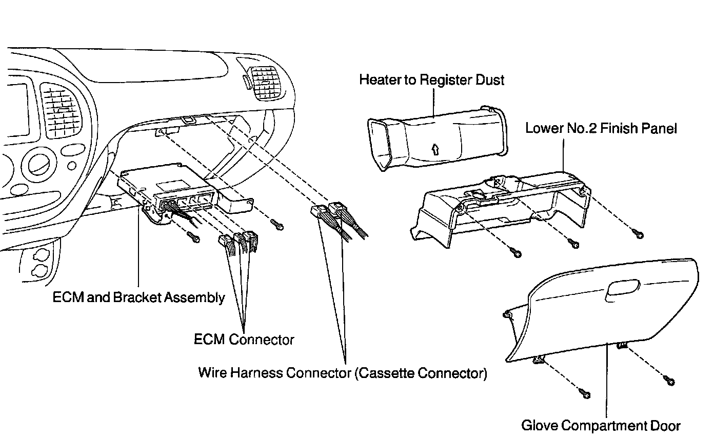
13. DISCONNECT ENGINE WIRE FROM CABIN
a. Remove the glove compartment door.
b. Remove the lower No.2 panel.
c. Remove the 3 screws, and disconnect the ECM from the body bracket.
d. Disconnect the 3 wire harness connectors from the ECM.
e. Disconnect the 2 wire harness connectors (cassette connector).
f. Disconnect the engine wire from the engine wire bracket and remove the 2 nuts, bolt and bracket.
g. Pull out the engine wire from the cowl panel.
14. DISCONNECT HOSES, WIRES, CONNECTORS, CLAMPS, GROMMET AND CABLES
a. Disconnect the accelerator cable from the engine.
b. Disconnect the 2 PS air hoses from hose clamp on the No.3 RH timing belt cover.
c. Disconnect the generator wire.
d. Disconnect the generator connector.
e. Disconnect the hose clamp for the PS air hose.
f. Disconnect the PS air hose from the upper intake manifold.
g. Disconnect the 2 heater hoses.
h. Disconnect the ground strap from the cowl panel.
i. Disconnect the fuel inlet hose and clamps.
j. Disconnect the fuel return hose and clamp.
k. Disconnect the air inlet hose from the charcoal canister.
l. Disconnect the EVAP hose from the charcoal canister.
m. w/o Hydraulic brake booster: Disconnect the brake booster tube.

15. w/ A/C: DISCONNECT A/C COMPRESSOR FROM ENGINE
a. Disconnect the A/C compressor connector.
b. Remove the 3 bolts, and disconnect the A/C compressor from the engine.
HINT: Suspend the A/C compressor securely.

16. DISCONNECT PS PUMP FROM ENGINE
Remove the 3 bolts, and disconnect the PS pump from the engine.
HINT: Suspend the PS pump securely.
17. REMOVE OIL COOLER PIPES FOR TRANSMISSION
a. Remove the 3 bolts and 3 stays.
b. Loosen the 2 union nuts, and remove the 2 oil cooler pipes.
18. REMOVE ENGINE ASSEMBLY FROM VEHICLE
a. Attach the engine chain hoist to the engine hangers.

b. Remove the 4 bolts holding the engine mounting brackets to the frame brackets.

c. Lift the engine out of the vehicle slowly and carefully.
HINT: Make sure the engine is clear of all wiring, hoses and cables.
d. Place the engine and transmission assembly onto the stand.

19. REMOVE DRIVE PLATE
Remove the 8 bolts, front spacer, drive plate and rear spacer.
INSTALLATION
1. INSTALL DRIVE PLATE
HINT: The mounting bolts are tightened in 2 progressive steps (steps c and e). If any one of the mounting bolts is broken or deformed, replace it.

a. Apply adhesive to 2 or 3 threads of the mounting bolt end.
Adhesive: Part No. 08833-00070, THREE BOND 1324 or equivalent

b. Install the front spacer, drive plate and rear spacer on the crankshaft.
c. Install and uniformly tighten the 8 mounting bolts in several passes, in the sequence shown.
Torque: 49 Nm (500 kgf-cm, 36 ft. lbs.)
If any one of the mounting bolts does not meet the torque specification, replace the mounting bolt.

d. Mark the mounting bolt with paint.
e. Retighten the mounting bolts by 90° in the numerical order shown.
f. Check that the painted mark is now at a 90° angle to (e).
2. INSTALL ENGINE ASSEMBLY IN VEHICLE
a. Attach the engine chain hoist to the engine hangers.

b. Slowly lower the engine assembly into the engine compartment.
c. Attach the engine mounting brackets to the frame brackets.
d. Install the engine mounting brackets to the frame brackets with the 2 nuts and 4 bolts.
Torque: 38 Nm (388 kgf-cm, 28 ft. lbs.)
e. Remove the engine chain hoist.
3. INSTALL PS PUMP
Install the PS pump with the 3 bolts.
Torque: 17 Nm (175 kgf-cm, 13 ft. lbs.)
4. w/A/C: INSTALL A/C COMPRESSOR
a. Install the A/C compressor with the 3 bolts.
Torque: 49 Nm (500 kgf-cm, 36 ft. lbs.)
b. Connect the A/C compressor connector.
5. CONNECT HOSES, WIRES, CONNECTORS, CLAMPS, GROMMET AND CABLES
a. Connect the accelerator cable to the engine.
b. Connect the 2 PS air hoses to hose clamp on the No.3 RH timing belt cover.
c. Connect the generator wire.
d. Connect the generator connector.
e. Connect the hose clamp for the PS air hose.
f. Connect the PS air hose to the upper intake manifold.
g. Connect the 2 heater hoses.
h. Connect the ground strap to the cowl panel.
i. Connect the fuel inlet hose and clamps.
j. Connect the fuel return hose and clamp.
k. Connect the air inlet hose to the charcoal canister.
l. Connect the EVAP hose to the charcoal canister.
m. w/o Hydraulic brake booster: Connect the brake booster tube.

6. CONNECT ENGINE WIRE TO CABIN
a. Push into the engine wire through the cowl panel.
b. Install the engine wire bracket with the 2 nuts and bolt and connect the engine wire to the bracket.
c. Connect the 3 connectors to the ECM.
d. Connect the 2 wire harness connectors (cassette connector).
e. Install the ECM with the 3 screws.
f. Install the lower No.2 panel.
g. Install the glove compartment door.
7. INSTALL FAN PULLEY, FAN, FLUID COUPLING AND DRIVE BELT
a. Temporarily install the fan pulley, the fan and fluid coupling assembly with the 4 nuts.
b. Install the drive belt.
c. Tighten the 4 nuts holding the fluid coupling to the fan bracket.
8. INSTALL BATTERY CABLES
a. Connect the battery positive (+) terminal cable.
b. Connect the battery negative (-) cable to the battery and left fender apron.
c. Connect the clamp on battery negative (-) cable to No.2 relay box.
9. INSTALL AIR CLEANER AND INTAKE AIR CONNECTOR PIPE ASSEMBLY
a. Install the air cleaner case with the 3 bolts.
Torque: 5 Nm (51 kgf-cm, 44 inch lbs.)
b. Connect the intake air connector to the throttle body.
c. Connect the MAF meter connector.
d. w/ A/C: Install the suction hose to the intake air connector.
e. Connect the PS air hose, air inlet hose for EVAP, PCV hose and MAF meter connector to the intake air connector.
10. INSTALL THROTTLE BODY COVER
11. INSTALL TRANSMISSION
12. INSTALL RADIATOR ASSEMBLY
13. INSTALL FRONT STABILIZER BAR
14. INSTALL FRONT AND REAR PROPELLER SHAFTS
15. INSTALL FRONT EXHAUST PIPES
16. FILL WITH ENGINE COOLANT
17. FILL WITH ENGINE OIL
18. START ENGINE AND CHECK FOR LEAKS
19. INSTALL ENGINE UNDER COVERS
20. INSTALL HOOD
21. PERFORM ROAD TEST
Check for abnormal noise, shock, slippage, correct shift points and smooth operation.
22. RECHECK ENGINE COOLANT AND OIL LEVELS