Camshaft Bearing
INSTALL CAMSHAFTSNOTICE: Since the thrust clearance of the camshaft is small, the camshaft must be kept level while it is being installed. If the camshaft is not kept level, the portion of the cylinder head receiving the shaft thrust may crack or be damaged, causing the camshaft to seize or break. To avoid this, the following steps should be carried out.
a. Install the RH camshafts.
1. Apply MP grease to the thrust portion of the intake and exhaust camshafts.
2. Place the intake and exhaust camshafts.

3. Set the timing mark (1 dot mark) of the camshaft main gear at approximately 10° angle.
4. Remove any old packing (FIPG) material from front bearing cap.

5. Apply seal packing to the front bearing cap as shown in the illustration.
Seal packing: Part No. 08826-00080 or equivalent
- Install a nozzle that has been cut to a 1.5 mm (0.06 inch) opening.
- Parts must be assembled within 5 minutes of application. Otherwise the material must be removed and reapplied.
- Immediately remove nozzle from the tube and reinstall cap.
NOTICE: Do not apply seal packing to the front bearing cap grooves.

6. Install the front bearing cap.
HINT: Installing the front bearing cap will determine the thrust portion of the camshaft.
7. Install the other bearing cap in the sequence shown with the arrow mark facing forward.
HINT: Align the arrow marks at the front and rear of the cylinder head with the mark on the bearing cap.
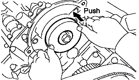
8. Push in the camshaft oil seal.

9. Apply a light coat of engine oil on the threads and under the heads (D and E) of the bearing cap bolts.
HINT: Do not apply engine oil under the heads of the bearing cap bolt (A), (B) and (C).
10. Install the oil feed pipe the 22 bearing cap bolts as shown.
HINT: Each bolt length is indicated in the illustration.
Bolt length:
25 mm (0.98 inch) for A
38 mm (1.50 inch) for B
52 mm (2.05 inch) for C
72 mm (2.83 inch) for D
94 mm (3.70 inch) for E

11. Uniformly tighten the 22 bearing cap bolts in several passes, in the sequence shown.
Torque:
Bolt A: 7.5 Nm (80 kgf-cm, 69 inch lbs.)
Others: 16 Nm (160 kgf-cm, 12 ft. lbs.)

12. Boring the service bolt installed in the driven subgear upward by turning the hexagon wrench head portion of the camshaft with a wrench.
13. Remove the service bolt.
b. Install the LH camshafts.
1. Apply MP grease to the thrust portion of the intake and exhaust camshafts.
2. Place the intake and exhaust camshafts.

3. Engage the intake gear to the exhaust gear by meeting the timing marks (2 dot marks) on each gear.

4. Remove any old packing (FIPG) material.
5. Apply seal packing to the front bearing cap.
Seal packing:Part No. 08826-00080 or equivalent
- Install a nozzle that has been cut to a 1.5 mm (0.06 inch) opening.
- Parts must be assembled within 5 minutes of application. Otherwise the material must be removed and reapplied.
- Immediately remove nozzle from the tube and reinstall cap.
NOTICE: Do not apply seal packing to the front bearing cap grooves.

6. Install the front bearing cap.
HINT: Installing the front bearing cap will determine the thrust portion of the camshaft.
7. Install the other bearing cap in the sequence shown with the arrow mark facing forward.
HINT: Align the arrow marks at the front and rear of the cylinder head with the mark on the bearing cap.

8. Push in the camshaft oil seal.

9. Apply a light coat of engine oil on the threads and under the heads (D and E) of the bearing cap bolts.
HINT: Do not apply engine oil under the heads of the bearing cap bolt (A), (B)and (C).
10. Install the oil feed pipe and 22 bearing cap bolts as shown.
HINT: Each bolt length is indicated in the illustration.
Bolt length:
25 mm (0.98 inch) for A
38 mm (1.50 inch) for B
52 mm (2.05 inch) for C
72 mm (2.83 inch) for D
94 mm (3.70 inch) for E

11. Uniformly tighten the 22 bearing cap bolts in several passes, in the sequence shown.
Torque:
Bolt A: 7.5 Nm (80 kgf-cm, 69 inch lbs.)
Others 16 Nm (160 kgf-cm, 12 ft. lbs.)

12. Boring the service bolt installed in the driven sub-gear upward by turning the hexagon wrench head portion of the camshaft with a wrench.
13. Remove the service bolt.